
Content last revised on March 11, 2026
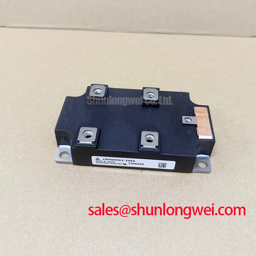
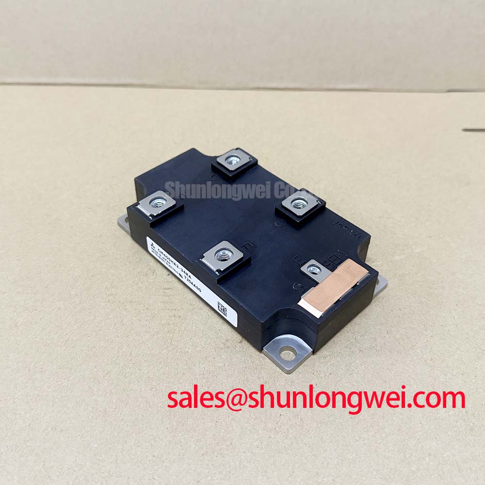
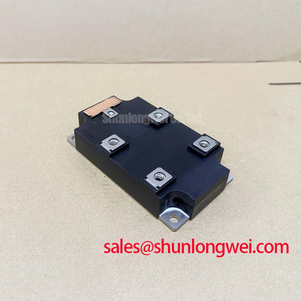
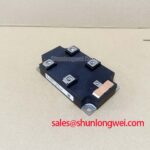
Mitsubishi CM400HA2-34KA: High-Efficiency 1700V IGBT Module
Product Overview: A Focus on Loss Reduction
The Mitsubishi CM400HA2-34KA H-Series IGBT module is engineered for superior power conversion efficiency in high-current, high-voltage applications. With its robust single-switch configuration, this device provides a foundational building block for designers aiming to minimize total power losses and enhance system power density. Its performance is defined by key specifications of 1700V | 400A | VCE(sat) 2.7V (max), delivering tangible benefits in reduced thermal load and improved operational economy. This module directly addresses the challenge of managing system heat by featuring a low collector-emitter saturation voltage, which fundamentally lowers conduction losses and simplifies the required thermal management hardware.
Aligning with Energy Efficiency Mandates
In today's industrial and renewable energy sectors, efficiency is not just a performance metric but a strategic imperative. The design of the CM400HA2-34KA directly supports system compliance with increasingly stringent energy regulations, such as those for IE3 and IE4 class industrial motors. By minimizing both conduction and switching losses, this IGBT module enables designers of Variable Frequency Drives (VFDs) and solar inverters to achieve higher efficiency ratings. This translates to lower lifetime operating costs for the end-user and contributes to broader corporate sustainability goals, making it a forward-looking choice for next-generation power electronics platforms.
Core Electrical and Thermal Parameters
Accurate system modeling and reliability forecasting depend on a clear understanding of key component parameters. The CM400HA2-34KA is characterized by a set of specifications optimized for demanding, high-power switching tasks. For a comprehensive list of specifications, performance curves, and application notes, please Download the Datasheet.
Parameter Interpretation
- Collector-Emitter Saturation Voltage (VCE(sat)): Think of VCE(sat) as the 'electrical friction' of the switch in its 'on' state. The CM400HA2-34KA's low maximum VCE(sat) of 2.7V means less energy is wasted as heat during conduction. This is analogous to a well-lubricated bearing minimizing mechanical friction, leading directly to higher overall system efficiency.
- Thermal Resistance (Junction-to-Case, Rth(j-c)): This value represents the module's ability to transfer heat from the active silicon chip to the module case. The low typical value of 0.058°C/W for the IGBT signifies an efficient thermal pathway, which is critical for maintaining a safe junction temperature under heavy electrical loads and ensuring long-term operational reliability. A detailed understanding of this parameter is crucial for effective heatsink design, a topic further explored in our guide to unlocking IGBT thermal performance.
| Parameter | Symbol | Test Conditions | Value |
|---|---|---|---|
| Collector-Emitter Voltage | VCES | - | 1700 V |
| Gate-Emitter Voltage | VGES | - | ±20 V |
| Collector Current (DC) | IC | TC = 25°C | 400 A |
| Collector-Emitter Saturation Voltage | VCE(sat) | IC = 400A, VGE = 15V | 2.7 V (max) |
| Collector Power Dissipation | PC | TC = 25°C | 2500 W |
Data for Your Design Matrix
Choosing the right power module requires a careful review of how key specifications align with system-level requirements. The data below is presented to facilitate your technical evaluation process. The optimal component selection depends on the specific priorities of your design, such as the required voltage safety margin, target efficiency, and thermal constraints.
| Parameter | CM400HA2-34KA | CM400HA-24H | Engineering Implication |
|---|---|---|---|
| Collector-Emitter Voltage (VCES) | 1700V | 1200V | Higher VCES provides a greater safety margin against voltage transients, essential for 690V line applications. |
| Collector Current (IC) | 400A | 400A | Both modules offer identical current handling capability. |
| VCE(sat) max. at nominal IC | 2.7V | 2.7V | Both provide similar on-state losses, shifting the selection focus to voltage rating and switching performance. |
For 600-900V DC-link systems requiring significant voltage overhead, the 1700V CM400HA2-34KA provides a superior safety margin compared to 1200V alternatives like the CM400HA-24H.
Proven in High-Power Conversion Stages
While specific customer deployments are proprietary, the architectural benefits of the CM400HA2-34KA lend themselves to several demanding fields. In multi-megawatt wind turbine converters, for instance, its single-switch topology enables flexible implementation within advanced multi-level inverter designs. This modularity is instrumental in achieving lower harmonic distortion and improved grid compatibility. Similarly, in high-power UPS systems, the module's high voltage rating and robust thermal performance are key to building resilient power backup solutions that can handle significant fault currents and maintain operational stability.
Inside the Low-Loss Switching Performance
What defines this module's efficiency? Its low VCE(sat) of 2.7V minimizes conduction state power dissipation. The total power loss in an IGBT module is a sum of conduction losses (when the switch is on) and switching losses (during turn-on and turn-off transitions). The CM400HA2-34KA is built on Mitsubishi's advanced silicon technology, likely a form of their Carrier Stored Trench Gate Bipolar Transistor (CSTBT™) technology, which optimizes the trade-off between VCE(sat) and switching speed. The low VCE(sat) directly reduces conduction losses (Pcond = VCE(sat) × IC). To fully leverage its switching characteristics, designers must implement a well-engineered Gate Drive circuit, as detailed in the component datasheet.
Empowering High-Voltage Industrial & Renewable Systems
Where is the CM400HA2-34KA best applied? In high-power inverters, motor drives, and renewable energy systems. The combination of a 1700V breakdown voltage and 400A current rating makes this module an excellent candidate for the core switching element in a variety of high-power applications. Its design is particularly well-suited for:
- AC & DC Motor Controls: Provides the necessary power handling and efficiency for large industrial drives, helping systems meet stringent energy performance standards.
- Uninterruptible Power Supplies (UPS): The high voltage rating and robust Safe Operating Area (SOA) ensure reliability in critical power backup infrastructure.
- Renewable Energy Inverters: In solar and wind power applications, its low-loss characteristics are vital for maximizing the energy harvested and improving the levelized cost of energy (LCOE).
- High-Power Switching Supplies: Serves as a reliable switch in applications such as industrial welding and induction heating where precise control of large currents is required.
Technical Questions on the CM400HA2-34KA
What is the primary benefit of the CM400HA2-34KA's 1700V rating in an application?
The 1700V collector-emitter voltage (VCES) provides a substantial safety margin for systems with high DC bus voltages (e.g., those derived from a 690VAC line), offering robust protection against transient overvoltages common in industrial environments and thereby enhancing long-term system reliability.
The datasheet specifies a maximum VCE(sat) of 2.7V. How does this value change with junction temperature?
Typically, the VCE(sat) of an IGBT like this exhibits a positive temperature coefficient. This means that as the junction temperature (Tj) increases during operation, the VCE(sat) will also tend to increase. Engineers must consult the characteristic curves in the official datasheet, a key step explained in our guide to decoding IGBT datasheets, to perform accurate loss calculations for their specific thermal and current profiles.
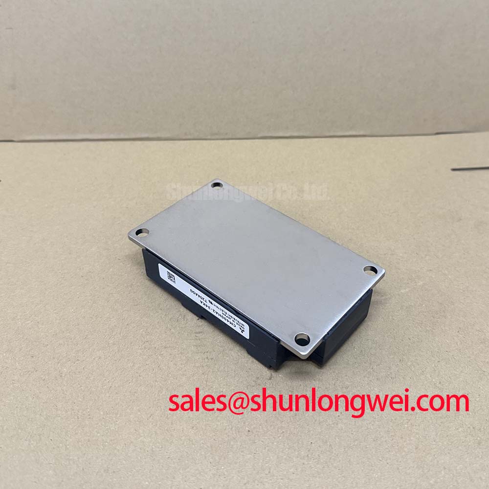
Is special consideration needed for mounting a single IGBT module to a heatsink?
Yes, proper mounting is critical to prevent device failure. To achieve the specified thermal resistance, ensure the heatsink surface is clean and meets the flatness requirements. Apply a thin, uniform layer of appropriate thermal interface material. Most importantly, tighten the mounting screws to the torque specified in the datasheet (3.5 - 4.5 N·m) using a calibrated torque wrench to prevent uneven pressure, which can create thermal voids and lead to catastrophic overheating.
Integrating Efficiency into Your Next Power System
The Mitsubishi CM400HA2-34KA offers a potent combination of high voltage rating, significant current capacity, and efficiency-focused design. To facilitate your design-in process, we recommend a thorough review of the official datasheet for detailed performance curves and application guidance. Should you require further assistance in evaluating how this module can meet the specific efficiency and reliability targets of your project, our technical specialists are available to provide an engineering-level consultation.