

Content last revised on October 23, 2026
CM1200DU-24H Circuit Protection & Reliability: Mitigating Commutation Turn-Off Voltage Spikes
With the DC link isolated and verified discharged, disconnect external current paths before comparing collector-to-emitter and gate-to-emitter readings on the removed CM1200DU-24H. Record meter polarity and terminal connections: connected snubbers, gate-driver components, and parallel power paths can alter a cold measurement. A persistent low-resistance reading warrants further investigation, but a handheld meter cannot establish switching performance or prove serviceability under load.
The Mitsubishi Electric CM1200DU-24H IGBT module has a collector-emitter voltage rating of 1200 V and a DC collector-current rating of 1200 A at a case temperature of 60°C—both Official Specifications. For repair assessment, retain that case-temperature condition alongside the current rating. Match the equipment schematic, terminal arrangement, driver requirements, and cooling assembly before treating another module as a compatible replacement.
Capture the collector-emitter voltage and commutating current together when investigating switching overshoot. Design Consideration: diode reverse recovery and IGBT turn-off are related commutation events, but they require separate interpretation. Reverse recovery occurs as the conducting diode is driven into blocking; rapid current interruption during IGBT turn-off produces another source of voltage stress. Distinguishing these events prevents an ineffective gate-resistor adjustment from masking the actual problem.
Use appropriately rated differential voltage and current probes, with measurement connections that minimize pickup. Examine the recovery-current peak, its decay, and the accompanying voltage ringing under controlled operating conditions. Peak reverse-recovery current, I_rrm, is meaningful only with its associated current, temperature, and commutation conditions. Abrupt recovery can excite the power-loop parasitics; a ringing trace alone does not establish that the module has deteriorated.
For the incoming switch, adjusting turn-on gate resistance can moderate commutation speed, but the resulting switching loss and driver loading need assessment. An RC snubber offers another damping mechanism when its placement addresses the oscillating loop. Designers should determine resistance, capacitance, pulse capability, and thermal loading from measured behavior rather than transferring values from a different converter. Keep the snubber connection compact without compromising terminal clearance or access for fastening.
A MOV-based overvoltage network should be assessed separately from the local switching snubber. Its clamping behavior, energy capability, connection inductance, and coordination with upstream protection determine its contribution during abnormal events; it is not a substitute for a controlled commutation path. The Mitsubishi Electric Diode Modules Lineup provides manufacturer context for diode product selection, not a reverse-recovery specification for this IGBT module. For a separate technology comparison, The 1200 V CoolSiC™ MOSFET Advantage in Three-Phase Power Conversion discusses SiC conversion considerations; its device behavior should not be transferred to the CM1200DU-24H.
Field Diagnostics & Commissioning: Calculating Failures-in-Time Rates in High-Altitude CM1200DU-24H Applications
Record the installation altitude, actual blocking-voltage profile, and operating duty before requesting a cosmic-ray reliability assessment. Design Consideration: an elevated-site evaluation should use a manufacturer-supported neutron-induced failure model appropriate to the device and operating conditions. Neither the voltage class nor a cold terminal test supplies a valid single-event burnout rate. A FIT calculation requires applicable susceptibility data, environmental assumptions, and time spent at each relevant blocking condition.
Keep any proposed DC-bus derating tied to that assessment rather than assigning a universal altitude correction. The maintenance record should distinguish steady blocking voltage from measured switching excursions and identify the cooling conditions used during testing. These observations help the equipment designer evaluate voltage headroom without converting an unsupported reliability assumption into a replacement specification.
At the terminal assembly, compare the module connection drawing with the equipment schematic and identify every power and gate connection before reconnecting busbars. Inspect insulating barriers, contamination tracks, displaced washers, and conductor edges. The 2500 V AC for 1 minute isolation voltage is an Official Specification; it does not establish the required creepage or clearance of the complete assembly. Those distances depend on the equipment insulation design, operating environment, and applicable standards.
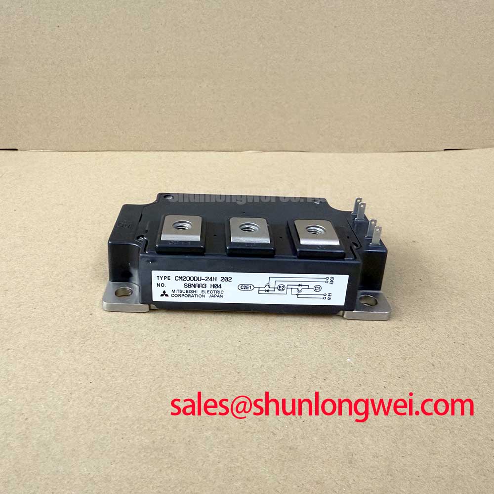
Assess busbar fastening for contact integrity and mechanical strain using the equipment’s approved hardware and assembly procedure. Unsupported busbar weight or misaligned conductors can load terminals even when a fastener appears secure. For procurement comparison, the CM200DU-24H is a separate model to evaluate against its own ratings, dimensions, and terminal drawing—not an automatic substitute. A utility-scale centralized battery energy storage PCS is one possible compatibility assessment context, subject to its converter schematic, cooling capacity, and protection requirements. Mitsubishi Electric’s NX-Series IGBT Modules likewise represent a separate product family whose mechanical and electrical interfaces require independent comparison.
Field Diagnostics & Commissioning: Baseplate Seating and Screw Tightening for CM1200DU-24H Modules
Inspect the heatsink contact surface for residual compound, burrs, scratches, and distortion before installing the module. Design Consideration: thermal-interface material fills surface irregularities; it should not be used to conceal a damaged mounting surface or compensate for an incorrectly fitted cooling assembly. Evaluate baseplate seating against the applicable mechanical drawing and assembly procedure rather than attempting to flatten the module with mounting screws.
Control thermal-compound deposition through the equipment’s qualified application method. The target bond line should reflect the interface material, surface condition, contact area, and clamping arrangement. A generic film-thickness range is not a CM1200DU-24H factory requirement. During process qualification, a contact-transfer inspection can help reveal uneven coverage or trapped gaps, provided the surfaces are subsequently cleaned and the interface is reapplied before service installation.
Bring mounting screws into engagement without forcing alignment, then follow the approved tightening sequence and torque specification. Progressive, distributed tightening can help seating when required by the assembly procedure, but screw size alone does not establish the correct torque for this module. Field Alert: Do not pull a misaligned busbar into position with the module terminal screws; correct the conductor alignment before tightening.
The junction-to-case thermal resistance of 0.015 K/W per IGBT is an Official Specification. It describes the device’s junction-to-case thermal path, not the complete path through the interface and heatsink to coolant or ambient air. During commissioning, compare case-temperature behavior under repeatable loading and cooling conditions. An unexpected rise should prompt checks of interface contact, airflow or coolant performance, and electrical loss rather than an immediate conclusion about internal damage.
Benchtop Waveform Tuning: Mitigating Stress via Junction-to-Case Thermal Network Simulation on CM1200DU-24H
Reconstruct the actual overload pulse train before estimating peak junction temperature. Engineering Recommendation: combine conduction and switching losses over the operating sequence, then apply the manufacturer’s transient thermal response or a thermal network fitted to that response. A multi-RC model needs documented coefficients and a stated network form; arbitrary time constants can produce a plausible temperature trace without representing this module.
For a steady-state check, the Engineering Calculation is junction temperature approximately equal to case temperature plus per-IGBT dissipation multiplied by 0.015 K/W. Pulsed operation requires the time-dependent thermal response instead. Include the temperature remaining from earlier pulses, measured case-temperature movement, and the cooling interval when evaluating repetitive overloads. The maximum junction temperature of 150°C is an Official Specification, not a recommended operating target.
When parallel switching paths are present in the equipment, assess current sharing from measured branch currents and matched operating conditions. A presumed positive temperature coefficient does not establish balanced operation across the full current and temperature range. Gate-path differences, connection impedance, cooling asymmetry, and switching timing can affect dynamic sharing even when static readings are similar.
Do not substitute the DC collector-current rating for a diode surge-current limit or an overload recovery window. Evaluate diode stress using the applicable surge ratings and thermal history, then confirm the controller’s restart behavior against the equipment protection strategy. During waveform tuning, retain captures of current, collector-emitter voltage, gate behavior, and case temperature so the revised switching settings can be assessed for both reduced electrical stress and increased dissipation.