Content last revised on September 22, 2026
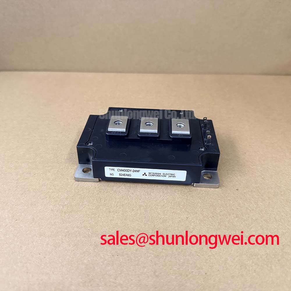
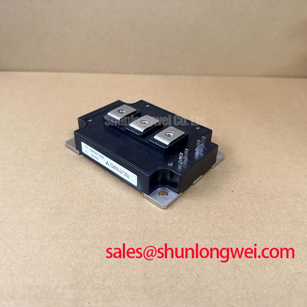
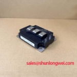
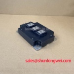
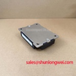
Mitsubishi CM400DY-24NF Dual IGBT Module: 1200V 400A Power Control
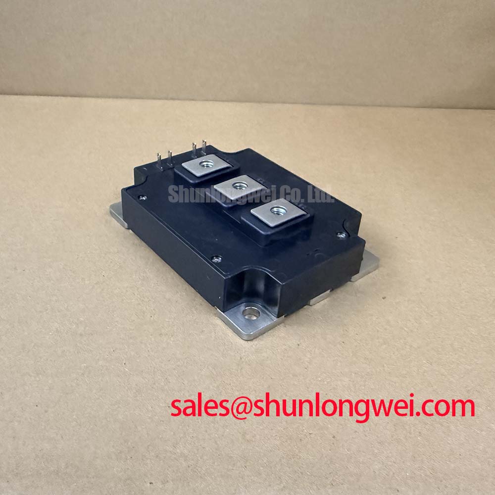
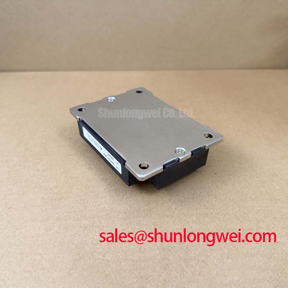
The CM400DY-24NF dual IGBT module offers high thermal reliability and low switching losses, making it an excellent fit for demanding power conversion topologies. Rated at 1200V and 400A with a power dissipation of 1470W, this half-bridge module is built for efficiency. Engineers benefit from lower power losses during switching and simplified thermal management. For 1200V motor drive applications requiring optimal thermal dissipation and high reliability, this 400A module is the ideal choice.
Application Scenarios & Value
Achieving Thermal Efficiency in Inverters and Servo Controls
Engineers often face severe thermal stress issues when designing high-frequency induction heating systems or heavy industrial motor drives. Under continuous load, transient current spikes can degrade traditional planar silicon devices due to localized heat concentration. The CM400DY-24NF, featuring a low junction-to-case thermal resistance of 0.085 K/W, prevents thermal runaway by efficiently transferring heat to the copper baseplate. This makes it highly suitable for general-purpose inverters, servo controls, and uninterruptible power supplies (UPS).
For systems that require lower current handling, the related CM300DY-24NF or CM200DY-24NF modules can be evaluated to achieve optimal cost-performance ratios without altering the physical packaging dimensions.
Technical Deep Dive
Trench Gate CSTBT Design for Enhanced Switching Performance
At the core of the CM400DY-24NF is the carrier-stored trench-gate bipolar transistor (CSTBT™) technology. Think of the CSTBT™ structure as an optimized highway toll booth system. Instead of charge carriers slowing down and creating a bottleneck (which represents conduction loss), the carrier storage layer acts like a pre-pass lane, maintaining a high density of charge carriers near the emitter. This significantly lowers the collector-emitter saturation voltage (VCE(sat)) to a typical 2.1V at 25°C and 1.8V at 125°C.
Similarly, the module's thermal resistance acts like the diameter of a drainage pipe in a cooling loop. A wider pipe allows faster fluid flow. With a junction-to-case thermal resistance of 0.085 K/W for the IGBT portion and 0.15 K/W for the free-wheeling diode (FWDi), the module acts like a wide thermal highway, keeping the internal junction temperature well below its 150°C maximum limit. By integrating Mitsubishi CSTBT™ technology, the module minimizes both static and dynamic losses. For those looking to optimize their drive topology, a complete engineering guide is available in our in-depth analysis of IGBT modules. Proper selection of gate resistance is also vital, and designers can learn more about configuring gate drives by reading our guide to IGBT design integration.
Key Parameter Overview
Analyzing Critical Ratings and Characteristics
The following table outlines the key electrical and thermal parameters of the CM400DY-24NF half-bridge module, highlighted to support system-level design evaluations:
| Parameter | Symbol | Value / Rating | Conditions |
|---|---|---|---|
| Collector-Emitter Voltage | VCES | 1200V | Tj = 25°C, VGE = 0V |
| Continuous Collector Current | IC | 400A | Tc = 111°C |
| Maximum Power Dissipation | Pc | 1470W | Tc = 25°C (IGBT Part) |
| Collector-Emitter Saturation Voltage | VCE(sat) | 2.1V (typ) / 1.8V (typ) | Tj = 25°C / 125°C, IC = 400A |
| Diode Forward Voltage | VEC | 1.8V (typ) / 3.2V (max) | IE = 400A, VGE = 0V |
| Junction-to-Case Thermal Resistance | Rth(j-c)Q | 0.085 K/W | Per 1/2 IGBT module |
| FWDi Thermal Resistance | Rth(j-c)R | 0.15 K/W | Per 1/2 FWDi module |
| Isolation Voltage | Viso | 2500V AC | f = 60Hz, AC 1 minute |
Download the CM400DY-24NF datasheet for detailed specifications and performance curves.
Industry Insights & Strategic Advantage
Evaluating Long-Term TCO in the Era of High-Efficiency Electrification
In modern industrial automation and renewable energy grids, switching devices must meet strict efficiency regulations such as the IEC 61800-9-2 standard. Standardizing on dual IGBT Module packaging provides a reliable upgrade path for existing motor drive hardware. By reducing total power dissipation and operational thermal stress, the CM400DY-24NF directly contributes to lowering the total cost of ownership (TCO) of industrial systems. The robust construction and predictable degradation curves of the CSTBT™ chips ensure that maintenance cycles are extended, protecting critical machinery from unexpected outages.
FAQ
Addressing Common Integration Challenges and Concerns
What is the primary benefit of the CSTBT™ design?
It reduces conduction losses while maintaining robust short-circuit ruggedness.
How does the module improve thermal heat dissipation?
By utilizing an isolated copper baseplate that reduces thermal contact resistance.
Is the CM400DY-24NF suitable for retrofitting older industrial VFDs?
Yes. Its standard package footprint and dual configuration allow engineers to integrate it directly into existing chassis layouts, provided the gate drive circuits are calibrated for its input capacitance of 94nF.
What gate drive considerations are needed for CM400DY-24NF switching?
Designers should select a gate driver capable of supplying sufficient peak current to charge the 94nF input capacitance, using the recommended gate resistance of 0.78Ω to control switching speed.