
Content last revised on February 27, 2026
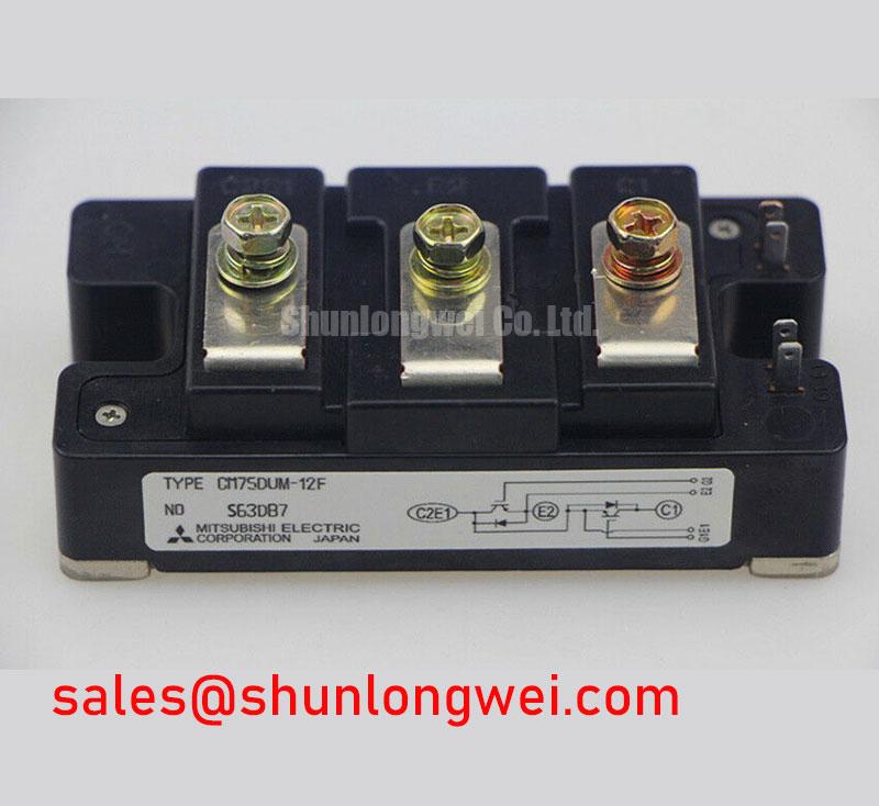
CM75DUM-12F Mitsubishi 600V 75A 6-Pack IGBT Module
The CM75DUM-12F is a high-performance 6-unit IGBT module (3-phase bridge configuration) designed by Mitsubishi Electric. Leveraging advanced CSTBT™ (Carrier Stored Trench-gate Bipolar Transistor) technology, this module is engineered to provide superior switching efficiency and reduced power dissipation in compact industrial applications. With a Collector-Emitter Voltage (Vces) of 600V and a Collector Current (Ic) of 75A, it serves as a critical building block for low-to-medium power motor control and energy conversion systems. For engineers prioritizing thermal management and high-density integration, the CM75DUM-12F integrates a dedicated NTC thermistor for real-time temperature monitoring, ensuring operational safety under varying load conditions. For industrial servo drives requiring precise control and low switching losses, the CM75DUM-12F provides an optimized 600V/75A solution.
Application Scenarios & Value
Maximizing Efficiency in Compact 3-Phase Inverter Designs
The CM75DUM-12F is purpose-built for Variable Frequency Drives (VFD) and Servo Drive systems where space and energy efficiency are non-negotiable. By consolidating six IGBTs into a single U-series package, designers can significantly reduce the PCB footprint and simplify the complexity of the Gate Drive layout. The low Collector-Emitter Saturation Voltage (Vcesat) of approximately 1.6V (at 25°C) directly translates to lower conduction losses, which is vital for systems operating in thermally constrained environments.
In high-fidelity engineering scenarios, such as a multi-axis robotic controller, the CM75DUM-12F handles rapid Switching Loss transitions with minimal EMI, meeting the rigorous demands of IEC 61800-3 standards. The integrated Kelvin Emitter terminals further enhance switching performance by isolating the power circuit from the control signals, preventing gate-signal oscillation. For systems requiring higher current handling or 1200V capability, the related CM150DU-24F or the CM200DY-24NF offer expanded overhead for heavy-duty industrial lines. To understand the underlying mechanics of these components, engineers can refer to Deconstructing the IGBT: A Deep Dive into Its Hybrid Structure.
Key Parameter Overview
Decoding the Specs for Enhanced Thermal Reliability
The following technical data reflects the baseline performance of the CM75DUM-12F under standard operating conditions. These values are critical for determining the Safe Operating Area (SOA) and selecting appropriate cooling solutions.
| Parameter Description | Symbol | Rated Value / Unit | Engineering Significance |
|---|---|---|---|
| Collector-Emitter Voltage | Vces | 600V | Maximum voltage headroom for 240V AC line applications. |
| Continuous Collector Current | Ic | 75A | Defines the sustained current capacity at Tc=80°C. |
| Saturation Voltage | Vce(sat) | 1.6V (typ.) | Determines conduction efficiency during the "on" state. |
| Total Power Dissipation | Ptot | 250W | The thermal limit for the module per IGBT element. |
| Internal NTC Thermistor | R25 | 5kΩ (typ.) | Enables precise Thermal Management and protection. |
| Isolation Voltage | Visol | 2500V AC | Ensures dielectric safety between the circuit and heatsink. |
Detailed failure diagnosis techniques can be explored in our guide on IGBT Failure Analysis.
Technical & Design Deep Dive
The CSTBT™ Advantage in High-Speed Switching Efficiency
The CM75DUM-12F utilizes Mitsubishi's proprietary CSTBT™ architecture, which represents a generational leap over standard IGBT Module designs. Think of the CSTBT™ structure like a high-flow plumbing valve that requires very little pressure to open but allows maximum flow once active. By optimizing the carrier distribution within the trench gate, Mitsubishi has achieved a "sweet spot" between Vcesat and turn-off energy ($E_{off}$). This allows the CM75DUM-12F to operate at higher carrier frequencies without the typical thermal penalties associated with switching losses.
Furthermore, the Reverse Bias Safe Operating Area (RBSOA) of this module is ruggedly defined, allowing it to withstand high $dv/dt$ events common in inductive load switching. The engineering benefit here is two-fold: reduced need for oversized passive filters and a significant improvement in the Power Cycling Capability. For designers transitioning from discrete solutions, integrating an IPM (Intelligent Power Module) or a 6-pack module like the CM75DUM-12F simplifies the Thermal Design by providing a single, predictable thermal interface (Rth) rather than multiple discrete points of failure.
Industry Insights & Strategic Advantage
Sustainability and the Shift Toward High-Density Power Electronics
The industrial landscape is moving rapidly toward Industry 4.0 standards, where energy efficiency is no longer optional—it is a regulatory requirement. The CM75DUM-12F aligns with global trends favoring decentralization and miniaturization of motor control. By reducing the energy lost as heat, this module supports the development of "green" UPS (Uninterruptible Power Supply) systems and high-efficiency medical equipment. For procurement specialists, the choice of a Mitsubishi U-series module ensures a reliable supply chain history and a technology path that mirrors the evolution of the Electric Vehicle (EV) Inverter market. Strategic insights into the broader market can be found in the 2025-2026 Global IGBT Market Outlook.
FAQ
How does the integrated NTC thermistor in the CM75DUM-12F simplify system protection?
The integrated NTC provides a direct measurement of the module's internal substrate temperature. This eliminates the need for external, less accurate sensors on the heatsink, allowing the controller to trigger derating or shutdown protocols much closer to the actual silicon thermal limit, thereby maximizing safe power density.
What is the primary benefit of the CSTBT™ technology compared to standard Trench IGBTs?
CSTBT™ (Carrier Stored Trench-gate Bipolar Transistor) technology significantly lowers the Vce(sat) while maintaining excellent switching speeds. This results in a substantial reduction in total power losses, which is critical for maintaining high efficiency in Variable Frequency Drives.
Can the CM75DUM-12F be used in 480V AC industrial systems?
With a Vces of 600V, the CM75DUM-12F is ideally suited for 200V-240V AC input systems. For 480V or 690V systems, we recommend looking at 1200V or 1700V rated modules to provide adequate safety margins against voltage spikes and DC link fluctuations.
What gate drive voltage is recommended for optimal performance?
To ensure full saturation and minimal switching losses, a gate voltage ($V_{GE}$) of +15V is typically recommended. Using a Negative Gate Voltage (e.g., -5V to -10V) during the "off" state is also encouraged to prevent parasitic turn-on due to the Miller Clamp effect in high-noise environments.
As power conversion requirements continue to evolve toward higher frequencies and smaller form factors, the CM75DUM-12F remains a strategically sound choice for designers seeking a balance of proven reliability and cutting-edge silicon performance. Its integration of 6-pack topology and Thermal Management features provides a foundation for robust, long-service-life industrial HMIs and motor control units. For further technical assistance or to verify technical compatibility with your current gate drive topology, we encourage engineers to review our Field Engineer's Handbook and resources on IGBT Design and Integration.