
Content last revised on July 10, 2026
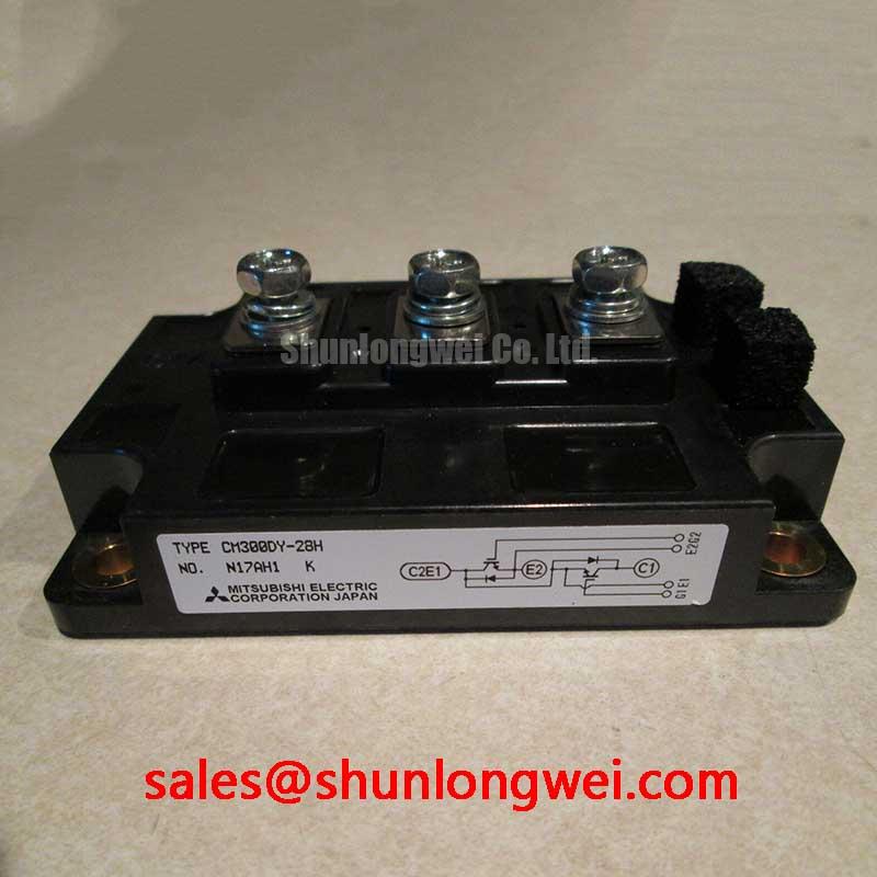
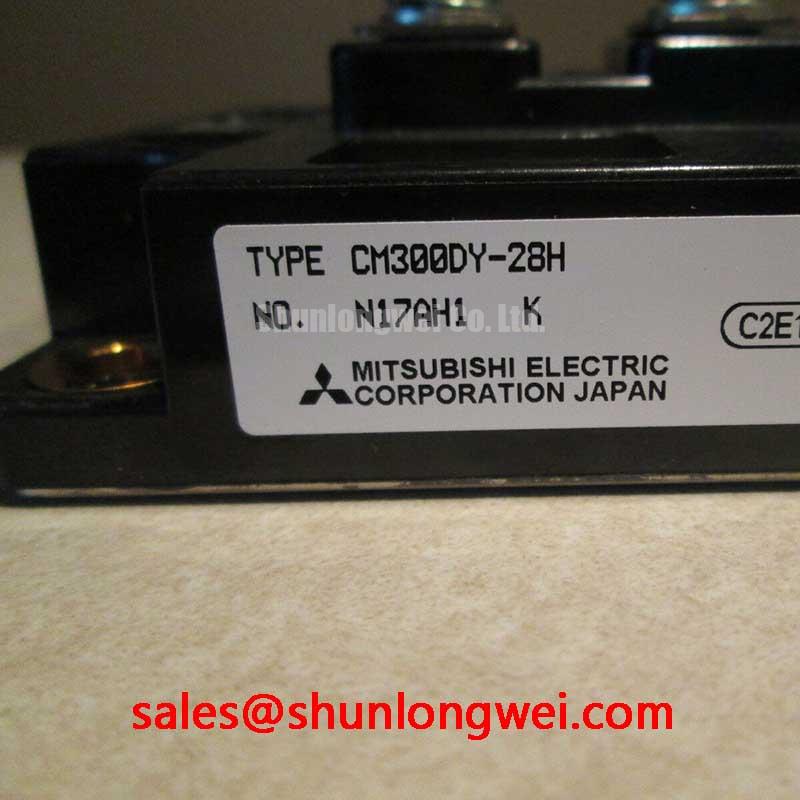
CM300DY-28H 1400V/300A Dual IGBT Module: Technical Analysis
The Mitsubishi Electric CM300DY-28H is a dual IGBT module from their H-Series, specifically engineered to provide superior switching performance in high-voltage, high-frequency power systems. This module integrates two IGBTs in a half-bridge configuration, offering core specifications of 1400V and 300A, combined with the low switching energy characteristic of the H-Series. Its primary engineering benefits are the significant reduction of power loss at high frequencies and the enablement of more compact, power-dense system designs. For engineers developing high-frequency industrial drives or solar inverters that operate with elevated DC link voltages, this module is an optimal choice for balancing efficiency and power density.
Application Scenarios & Value
System-Level Advantages in High-Frequency Power Conversion
For engineers designing high-power converters, the CM300DY-28H directly addresses the critical challenge of balancing efficiency, power density, and thermal performance. Consider its application in a modern Variable Frequency Drive (VFD). A primary goal in VFD design is often to increase switching frequency to reduce the size of magnetic components and improve motor control accuracy. However, higher frequencies typically lead to greater switching losses, which generate more heat. The CM300DY-28H, as an H-Series module, is optimized for low switching losses (Eon and Eoff). This characteristic is crucial; it means less energy is dissipated as heat during each turn-on and turn-off cycle. The direct engineering benefit is a cooler-running system, which allows for the use of smaller, more cost-effective heatsinks or enables higher current throughput for a given thermal solution. This contributes to a lower total cost of ownership and a more compact final product. Its 1400V collector-emitter voltage rating provides a robust safety margin for systems operating on high DC bus voltages, making it a reliable choice for demanding applications like industrial servo drives, uninterruptible power supplies (UPS), and welding equipment. For systems that require higher current handling in a similar voltage class, designers might also consider the CM600DY-24H.
Key Parameter Overview
Electrical and Thermal Characteristics for Performance Modeling
The technical specifications of the CM300DY-28H are foundational for accurate system modeling and performance prediction. The table below highlights the key parameters derived from the official datasheet. These values are essential for calculating losses, designing gate drive circuits, and implementing effective thermal management strategies.
| Parameter | Symbol | Value | Conditions |
| Collector-Emitter Voltage | VCES | 1400V | VGE = 0V |
| Collector Current (DC) | IC | 300A | TC = 25°C |
| Peak Collector Current | ICM | 600A | Pulsed |
| Collector-Emitter Saturation Voltage | VCE(sat) | Typ. 3.1V / Max. 4.2V | IC = 300A, VGE = 15V, Tj = 125°C |
| Maximum Power Dissipation | Pc | 2100W | TC = 25°C |
| Thermal Resistance (Junction-to-Case) | Rth(j-c) | Max. 0.083°C/W | Per IGBT |
| Isolation Voltage | Viso | 2500Vrms | AC 1 minute |
The parameters listed are based on the official datasheet and should be used for design evaluation. For complete electrical characteristics, performance curves, and test conditions, please refer to the official documentation.
Download the CM300DY-28H datasheet for detailed specifications and performance curves.
Technical Deep Dive
Analyzing the Impact of H-Series Technology on Switching Losses
The designation "H-Series" signifies that the CM300DY-28H is optimized for high-speed operation, which directly translates to lower Switching Loss. These losses, comprised of turn-on (Eon) and turn-off (Eoff) energy, are generated each time the IGBT transitions between its on and off states. To understand their importance, one can think of switching loss as the friction created when repeatedly opening and closing a heavy, un-oiled door; each movement requires a burst of effort and generates heat. A high-speed module like the CM300DY-28H is akin to a perfectly balanced and oiled door—it swings open and shut with minimal wasted energy, resulting in less heat generation per swing.
In parallel, conduction losses, dictated by the Collector-Emitter Saturation Voltage (VCE(sat)), are equally important for overall efficiency. Using a fluid dynamics analogy, VCE(sat) can be compared to the pressure drop across a valve in a pipeline. A low VCE(sat) is like a large, fully-open ball valve that allows water (current) to flow through with minimal resistance and pressure loss (voltage drop). A higher VCE(sat) is like a partially obstructed globe valve, creating more turbulence and wasting energy. The CM300DY-28H is engineered to balance these two loss mechanisms, providing a robust solution for applications where both high-frequency switching and efficient current conduction are paramount for effective Thermal Management.
Frequently Asked Questions (FAQ)
Engineering Questions on Implementation and Reliability
What is the primary advantage of the CM300DY-28H's 1400V rating compared to standard 1200V modules?
The 1400V VCES rating provides a significantly larger safety margin against overvoltage transients, which are common in industrial environments with long cable runs or large inductive loads. This makes it particularly suitable for systems connected to higher voltage DC links or for applications requiring enhanced reliability under harsh electrical conditions.
How do the low switching losses of the H-Series technology influence system design beyond just efficiency?
Lower switching losses directly reduce the heat dissipated by the module. This allows engineers to either increase the operating frequency to shrink the size and cost of magnetic components like inductors and transformers, or to increase the power output of the system while staying within the same thermal envelope. Both paths lead to higher power density, a key competitive advantage in modern power electronics.
What are key considerations for the gate drive circuit for this high-speed IGBT module?
For a high-speed module like the CM300DY-28H, the Gate Drive circuit is critical. It must be capable of supplying high peak currents to charge and discharge the gate capacitance quickly for sharp switching transitions. A low-inductance layout and the use of a negative gate voltage during the off-state are strongly recommended to prevent parasitic turn-on and ensure stable operation at high frequencies.
The strategic value of the CM300DY-28H lies in its ability to empower designers to push the boundaries of power density and efficiency. By providing a high-voltage, fast-switching component, it acts as an enabler for the next generation of more compact, reliable, and energy-efficient power conversion systems, from advanced motor controls to grid-tied renewable energy infrastructure.