


Content last revised on November 5, 2026
CM150DY-24A Operational Boundaries: Isolated Gate-Drive Supply Evaluation
- With the drive isolated and its DC link discharged, inspect the module terminals and surrounding insulation for contamination, looseness, or visible damage.
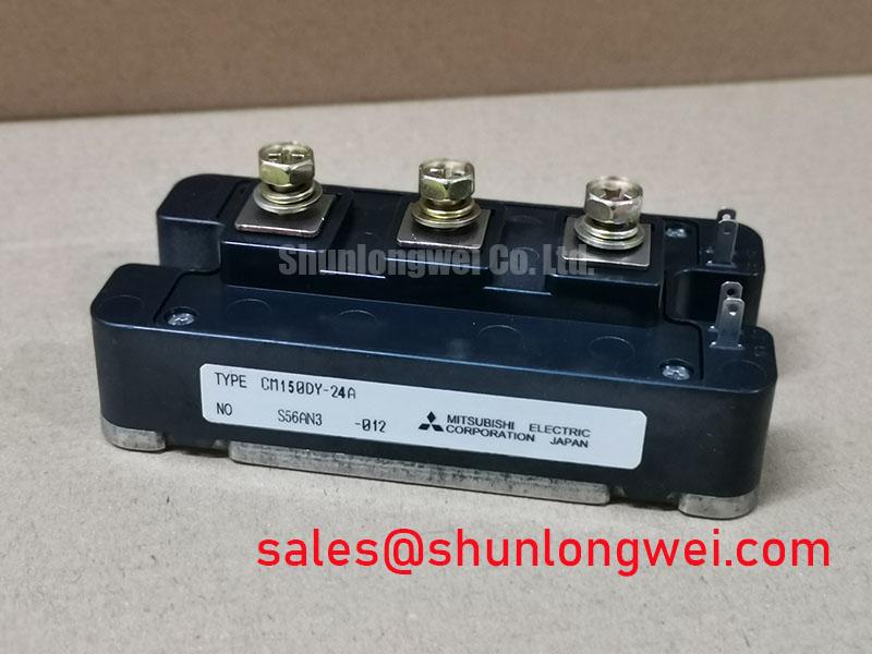
- Confirm that the installed part number is CM150DY-24A and that the equipment documentation calls for a 1200 V, 150 A Mitsubishi Electric IGBT module.
- Check that the module mounting surface, thermal interface, and heatsink are clean and correctly assembled before applying power.
- Inspect gate-drive wiring and isolation arrangements against the drive’s circuit documentation before reconnecting control power.
The CM150DY-24A is a Mitsubishi Electric IGBT module with an official rated voltage of 1200 V, a rated current of 150 A, and a module package. Those ratings identify important device-level boundaries; they do not, by themselves, establish allowable operating current in a particular drive. Switching frequency, current waveform, cooling conditions, gate drive, and the surrounding circuit all affect application performance. Treat the equipment schematic and the applicable manufacturer documentation as the references for pin assignment, switching characteristics, thermal limits, and installation details.
Start the gate-drive review at the isolation barrier between the control circuit and the module’s power stage. The barrier requirements belong to the complete drive design, not to the module’s stated 1200 V rating. Do not infer a reinforced-insulation rating or a common-mode transient immunity value for the CM150DY-24A from its voltage and current ratings. Select and verify the isolated gate-drive supply using the drive’s insulation coordination, operating environment, and applicable safety requirements.
During commissioning, compare the installed driver and its isolation components with the equipment documentation. Inspect PCB spacing and routing around the isolation boundary, paying attention to contamination, solder residue, damaged conformal coating, and cable routing that could compromise the intended separation. Required creepage and clearance depend on the system’s working voltage, pollution degree, material group, and applicable standard; they are not fixed by the module’s package designation. Apply the spacing rules specified for the actual equipment rather than treating a generic distance as a device specification.
False gate activity can arise from several parts of the system, including common-mode coupling, inadequate driver behavior, grounding arrangements, or excessive parasitic inductance in the gate loop. If the drive exhibits unexpected switching, inspect the control and emitter-reference paths and observe gate-to-emitter behavior with measurement equipment suitable for the circuit’s isolation and transient environment. A measurement setup with an unsuitable probe or reference can distort the waveform and create a hazardous connection. Record conditions and compare suspect behavior with a known-good channel or the original equipment test procedure.
Design Consideration: Keep each gate-drive loop compact and return its signal to the appropriate emitter reference; assess turn-off behavior and false triggering in the assembled drive, where coupling and parasitics are present.
For a heavy-duty variable-frequency AC motor drive, evaluate the module against the original circuit topology, cooling arrangement, and switching conditions before installation. The CM350DU-5F is another Mitsubishi Electric module that may appear in related selection work, but its different part number and ratings mean it is not an automatic substitute. Compare the full electrical, mechanical, and thermal requirements rather than selecting by brand or package alone. In a system-level power-stage review, the CM400HG-66X may also be relevant as a separate device; its role and compatibility depend on the actual schematic.
Mitsubishi Electric provides manufacturer information through its power semiconductors and high-power modules resource. Use the applicable product documentation to confirm terminal identification and device characteristics before repair or redesign. A different semiconductor technology does not share the same drive assumptions by default; engineers comparing switching approaches can consult ROHM’s SiC power devices and modules information as a separate technology reference.
Field Diagnostics & Commissioning: Output Filter and dv/dt Reactor Evaluation
For a motor drive with long output leads, examine the cable, motor, and output network as one transmission path. Reflections caused by impedance discontinuities can increase voltage stress at the motor terminals; the result depends on cable length and type, switching behavior, motor characteristics, and the drive’s output circuit. Do not assume a fixed peak voltage or treat a filter as a universal remedy. Review the drive and motor documentation, then capture terminal waveforms with a measurement setup rated and configured for the switching environment.
A dv/dt reactor and a sinusoidal output filter perform different roles. A reactor can reduce the rate of voltage change reaching the motor, while a sinusoidal filter is intended to produce a more nearly sinusoidal output under its specified operating conditions. Either option changes the electrical behavior seen by the inverter. Before adding one, check compatibility with the drive’s switching frequency, current, cable arrangement, protection functions, and motor insulation requirements. Selection and commissioning should follow the filter or reactor manufacturer’s application data and the drive manufacturer’s guidance.
When investigating a suspected output-related fault, document the motor-lead routing and length, inspect output terminals for signs of heating or looseness, and compare phase-to-phase behavior under controlled operating conditions. Use the same probe configuration and operating point when comparing measurements. A change after installing an output component should be assessed for its effect on current, temperature, protective trips, and motor-terminal waveforms, not only for a reduction in one observed voltage peak.
Mechanical installation also affects thermal performance. Remove residue from the module and heatsink mating surfaces, use a suitable thermal interface material, and follow the specified assembly procedure for the installed module and heatsink. Do not assume a universal interface thickness or tightening torque: the correct values depend on the component instructions and the mechanical design. Tighten fasteners in a controlled, even sequence where the assembly procedure calls for it, and avoid using the screws to pull a misaligned module onto the heatsink.
For equipment where motor-cable length or motor insulation has changed from the original configuration, treat the output network as a system-level compatibility question. Confirm that protection settings, cable construction, grounding, and any output filter remain appropriate for the drive. This is particularly relevant when a replacement module is being installed during a repair: restoring the original component does not correct an unrelated cable or filter change that may have contributed to the fault.
Transient Dynamics & Electrical Design: Baseplate and Thermal Interface
Uneven contact between the module baseplate and heatsink can impede heat transfer and place mechanical stress on the assembly. Before mounting the CM150DY-24A, inspect both mating surfaces for debris, burrs, corrosion, and visible distortion. Check flatness using the method and tolerance specified by the module and heatsink documentation; do not infer an allowable surface deviation from the module’s voltage or current rating.
Apply thermal interface material in accordance with the material and assembly instructions. Its purpose is to fill surface irregularities, not to compensate for a damaged or poorly fitted heatsink. Excess material, incomplete coverage, or uneven clamping can undermine the intended thermal contact. Position the module without sliding it across the prepared surface, then tighten the fasteners in the specified sequence and to the specified torque for the actual hardware. The mounting procedure is an assembly requirement, not an electrical rating of the IGBT module.
After installation, verify that the heatsink and cooling system are operating as intended before returning the drive to service. Under controlled load, monitor thermal behavior at the measurement points provided by the equipment design and compare results with the drive’s service limits. A temperature difference across phases or channels may justify checking contact pressure, interface coverage, airflow, and current sharing; it does not identify a single root cause on its own. Record the operating conditions so that measurements from later service work remain comparable.
Switching transients also depend on the power-loop layout. Minimize parasitic inductance in the commutation path and keep the gate-drive return arrangement consistent with the circuit design. During troubleshooting, inspect bus connections and module terminals for looseness or signs of arcing, then evaluate switching waveforms using the equipment’s approved procedure. If the DC-link arrangement or busbar geometry has been modified, reassess the resulting transient behavior instead of assuming that the original commissioning results still apply.
For broader background on wide-bandgap devices and their distinct integration considerations, see the Wide Bandgap Revolution guide. That discussion is a technology reference, not a specification for the silicon IGBT module. Keep device-specific decisions anchored to the CM150DY-24A documentation and the requirements of the complete drive.


