


Content last revised on June 28, 2026
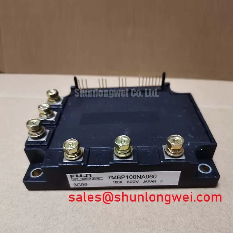
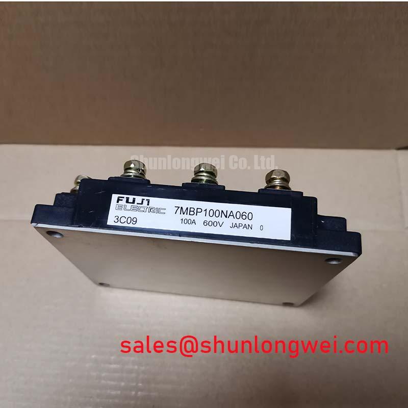
7MBP100NA060: Fuji Electric 600V 100A 7-in-1 IPM Module
Product Overview & Key Specifications
An Integrated Power Stage for Compact and Efficient Motor Drives
The Fuji Electric 7MBP100NA060 is a highly integrated Intelligent Power Module (IPM) designed to streamline the power stage of small to medium-sized motor control applications. This module consolidates a three-phase converter, a brake chopper, and a three-phase inverter into a single, compact package, offering a robust solution for systems requiring high efficiency and a reduced footprint. Key specifications include: 600V Collector-Emitter Voltage | 100A Continuous Collector Current | 2500V Isolation Voltage. Its primary engineering benefits are significant component reduction and simplified thermal management. The integrated nature of this Converter-Inverter-Brake (CIB) module directly addresses the engineering challenge of designing compact, reliable, and cost-effective Variable Frequency Drives (VFDs). For designers of compact, sub-7.5kW motor drives requiring high integration, the 7MBP100NA060 offers an optimal balance of performance and footprint.
Application Scenarios & Value
System-Level Benefits in Compact Motor Drive Applications
The 7MBP100NA060 is engineered for applications where space, assembly cost, and reliability are critical design drivers. Its most prominent use case is in low-power industrial automation, specifically for AC motor drives and servo drives up to approximately 7.5 kW. The module's 7-in-1 CIB topology presents a clear value proposition: it replaces up to seven discrete power semiconductor devices (and their associated gate drive and protection circuits) with a single component. This integration is crucial for engineers facing the challenge of fitting complex drive electronics into smaller enclosures. What is the key advantage of the 7-in-1 topology? It simplifies PCB layout and reduces assembly complexity, leading to lower manufacturing costs and improved system reliability by minimizing solder joints and potential points of failure. The module also includes a built-in thermistor, which allows for direct temperature feedback from the module's substrate. How does the built-in thermistor enhance reliability? It enables real-time temperature monitoring for over-temperature protection, a critical feature for ensuring robust operation in demanding industrial environments. For systems requiring a lower current rating within the same voltage class, the related 7MBP75RA060 offers a 75A alternative in a similar package.
Key Parameter Overview
Decoding Electrical and Thermal Specs for Optimal Performance
The performance of the 7MBP100NA060 is defined by its electrical and thermal characteristics, which are critical for system design and simulation. The parameters below are specified at a case temperature (Tc) of 25°C unless otherwise noted.
| Parameter | Symbol | Condition | Value |
|---|---|---|---|
| Inverter Part | |||
| Collector-Emitter Voltage | VCES | - | 600V |
| Gate-Emitter Voltage | VGES | - | ±20V |
| Collector Current (Continuous) | IC | Tc=80°C | 50A |
| Collector Current (Peak) | ICP | 1ms | 200A |
| Collector-Emitter Saturation Voltage | VCE(sat) | IC=100A | 2.1V (Typ.) / 2.7V (Max.) |
| Brake Part | |||
| Collector Current (Continuous) | IC | Tc=80°C | 25A |
| Collector-Emitter Saturation Voltage | VCE(sat) | IC=50A | 2.1V (Typ.) / 2.7V (Max.) |
| Converter Part (Diode) | |||
| Repetitive Peak Reverse Voltage | VRRM | - | 600V |
| Forward Current | IF(AV) | - | 100A |
| Module Characteristics | |||
| Isolation Voltage | Visol | AC, 1 minute | 2500V |
| Operating Junction Temperature | Tj | - | +150°C |
Technical Deep Dive
Understanding the CIB (Converter-Inverter-Brake) Advantage
The architecture of the Fuji Electric 7MBP100NA060 is a prime example of a CIB, or Converter-Inverter-Brake, module. This design paradigm is central to its value in motor control. The 'Converter' section is a three-phase diode bridge rectifier that converts the incoming AC line voltage into a DC bus. The 'Inverter' is a three-phase IGBT bridge that uses Pulse Width Modulation (PWM) signals to synthesize a variable frequency, variable voltage AC output to drive a motor. The 'Brake' section consists of a single IGBT and a freewheeling diode, which manages regenerative energy. When a motor decelerates, it acts as a generator, feeding energy back to the DC bus. The brake chopper dissipates this excess energy through an external resistor, preventing DC bus overvoltage faults. Combining these three essential functions into one thermally-efficient package reduces stray inductance between stages, which can lower voltage overshoots during switching and potentially simplify EMC filtering design. This is analogous to how a multi-chip module in a computer processor reduces signal path length to improve speed; here, the shortened power paths enhance electrical stability and reliability.
Frequently Asked Questions (FAQ)
What is the primary benefit of the module's VCE(sat) of 2.1V (typical) for the inverter stage?
A lower Collector-Emitter Saturation Voltage (VCE(sat)) directly translates to lower conduction losses during operation. With a typical VCE(sat) of 2.1V at its nominal 100A rating, the 7MBP100NA060 is designed for high efficiency. This reduces the amount of waste heat generated, which in turn allows for a smaller heatsink, contributing to a more compact and cost-effective overall system design. This parameter is a critical factor in the selection of IGBT modules for motor drives.
Is an external gate driver required for the 7MBP100NA060?
Yes, while this is an Intelligent Power Module (IPM) that includes IGBTs and diodes, it still requires an external gate drive circuit to provide the necessary control signals and isolated power. The module contains the power switching devices, but the control intelligence—including PWM signal generation, fault logic, and isolated gate power—must be implemented on the control board. The IPM's key advantage is the optimization of the internal power stage, not the complete elimination of all support circuitry. For further insights into simplifying power design, comparing IPMs with discrete solutions can be beneficial.
Design & Application Guidance
To ensure optimal performance and long-term reliability of the 7MBP100NA060, it is crucial to implement a properly designed interface and protection scheme. The module's integrated control circuit provides essential protections like over-current (OC) and under-voltage (UV) lockout. When an OC event is detected, the module signals a fault (Fo) output. The system's microcontroller must be programmed to interpret this fault signal and initiate a safe shutdown of the PWM signals to protect both the module and the motor. Effective thermal management is paramount; ensuring a low-resistance thermal path from the module's baseplate to the heatsink is essential for dissipating heat generated from switching and conduction losses.