

Content last revised on September 19, 2026
DCR1006SF2020 Specifications and Installation Considerations
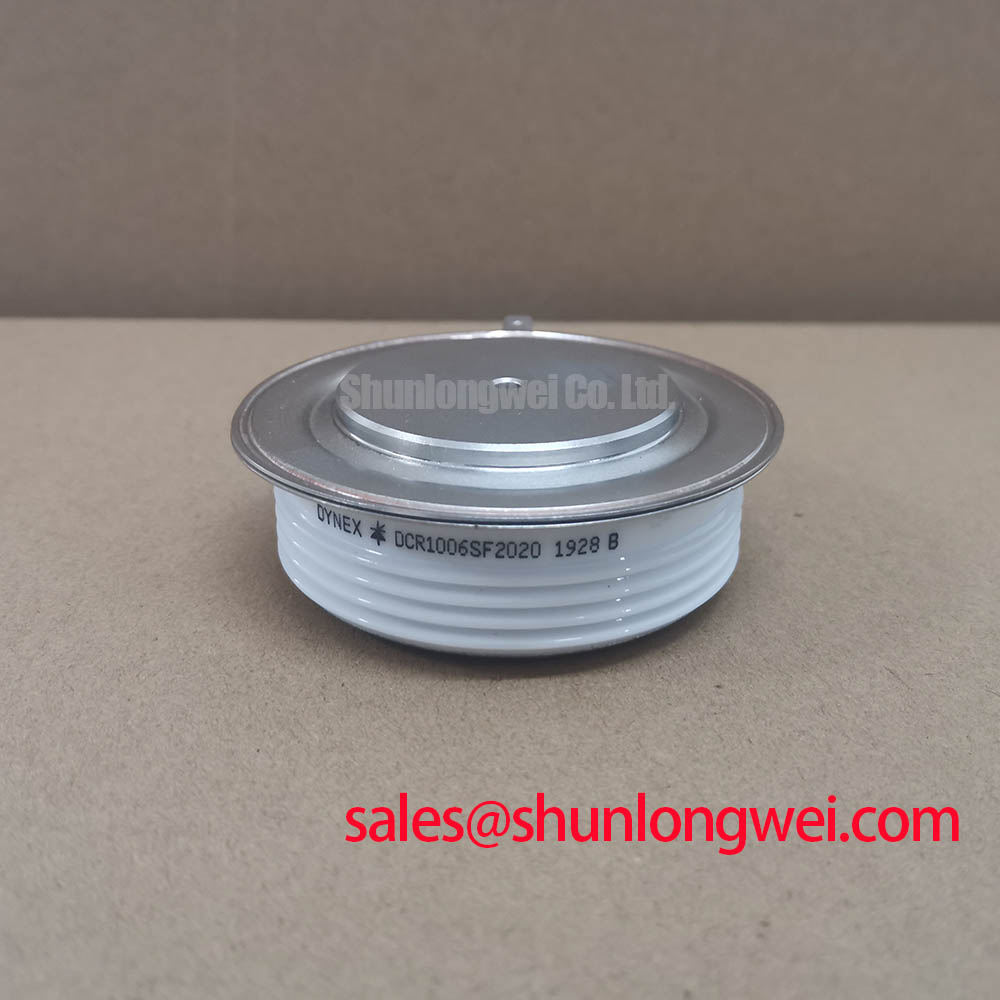
Before installation, verify the nameplate rating against the rectifier cubicle documentation and check the isolated device terminals for abnormal low-resistance paths while the assembly is fully disconnected and discharged. The DCR1006SF2020 is a Dynex thyristor module rated at VDRM and VRRM of 2000 V as an Official Datasheet Specification. Its current ratings are 1006 A average on-state current and 1580 A RMS on-state current, both specified at a heatsink temperature of 55°C with double-sided cooling.
For controlled high-current rectification, the module also has an Official Datasheet Specification of 200 mA gate trigger current at 25°C. The maximum junction temperature is 125°C. These values define the device boundary, but they do not replace verification of the actual firing circuit, busbar arrangement, semiconductor fuse coordination, cooling plates, and line-transient environment in the installed equipment.
| Official Datasheet Parameter | Value | Condition |
|---|---|---|
| Repetitive peak off-state voltage, VDRM and VRRM | 2000 V | Official Datasheet Specification |
| Average on-state current, IT(AV) | 1006 A | Heatsink at 55°C, double-sided cooled |
| RMS on-state current, IT(RMS) | 1580 A | Heatsink at 55°C, double-sided cooled |
| Peak non-repetitive surge current, ITSM | 19500 A | 10 ms half sine, junction at 125°C |
| Critical on-state current rise, di/dt | 300 A/µs | VDR at 1300 V, junction at 125°C |
| Thermal resistance, junction to heatsink, Rth(j-hs) | 0.019 K/W | Double-sided cooled |
| Maximum junction temperature, Tjmax | 125°C | Official Datasheet Specification |
| Gate trigger current, IGT | 200 mA | Junction at 25°C |
Assembly Integrity & Layout Architecture: Implementing AC Input Transient Overvoltage Clamping for DCR1006SF2020
Start at the AC input and trace the transient path to each DCR1006SF2020 terminal. A controlled rectifier can be exposed to switching disturbances from upstream transformers, contactors, capacitive banks, and line-side events. The module’s 2000 V repetitive peak off-state rating is an Official Datasheet Specification, not a statement that every installation transient is acceptable without a coordinated suppression network.
Design Consideration: place the surge-clamping and damping network so that the current loop between the protected AC conductors, suppression parts, and thyristor connections remains physically compact. A metal oxide varistor network can clamp high-energy line events, while an RC snubber can reduce the rate and amplitude of locally generated voltage excursions. Their selection must be based on measured installation conditions, AC supply characteristics, expected transient source impedance, and the rectifier topology. The system engineer should verify actual device-terminal voltage with correctly rated differential measurement equipment during commissioning.
Semiconductor fuse coordination should be reviewed as a complete fault-clearing path rather than as a current-rating comparison alone. Use the fuse manufacturer’s published pre-arcing and total clearing I²t information, then compare it against the rectifier branch configuration, prospective fault current, transformer contribution, and protection sequence. No fuse I²t limit is stated in the available official data for this module, so a module-specific value should not be assumed.
Terminal hardware requires equal attention. Clean, flat contact surfaces and balanced tightening across the current path help avoid localized resistance and uneven loading. The official data provided does not state terminal screw size or tightening torque. Installation personnel should therefore use the equipment manufacturer’s mechanical drawing and approved assembly instruction rather than applying a generic torque figure.
⚡ Safety Interlock Note: Isolate, lock out, and confirm discharge of the rectifier DC link before loosening any power or gate connection.
For a high-current green hydrogen electrolyzer DC power rectifier, these checks are particularly relevant when the original installation includes long AC feeders or high-energy transformer connections. This is a compatibility evaluation example, not a claim that the DCR1006SF2020 is specified for every electrolyzer rectifier design.
DCR1006SF2020 Circuit Protection & Reliability: Ensuring Uniform Heatsink Contact Pressure
The 0.019 K/W junction-to-heatsink thermal resistance is an Official Datasheet Specification under double-sided cooling. It is meaningful only when the installed thermal stack reproduces the required contact condition on both cooling faces. A cooling arrangement that contacts one side poorly, contains debris, or applies uneven force can increase thermal resistance beyond the stated condition and create unequal temperature distribution across the assembly.
During service replacement, inspect the cooling plates for burrs, corrosion residues, scratches, old hardened interface material, and local distortion. Apply thermal interface material according to the equipment builder’s documented process, then confirm that the module seats without rocking before final tightening. Design Consideration: use a controlled cross-pattern tightening sequence so contact pressure develops progressively and does not twist the module relative to either heatsink face.
The published maximum junction temperature is 125°C. It should be treated as an absolute device boundary, while the allowable operating thermal condition must be established by the actual converter duty cycle, coolant or heatsink temperature, conduction waveform, firing angle, and measured thermal behavior. A current rating of 1006 A IT(AV) and 1580 A IT(RMS) applies at a 55°C heatsink temperature with double-sided cooling; it cannot be transferred unchanged to a different cooling geometry.
Gate-circuit wiring should be routed separately from high-current power conductors wherever practical. The official 200 mA IGT rating identifies the trigger-current parameter at 25°C, but it does not define a complete gate-drive supply, pulse duration, isolation arrangement, or firing delay. Engineering Recommendation: validate gate pulse integrity at the module terminals under operating noise conditions, paying attention to pulse repeatability and timing symmetry across series or bridge positions.
Where engineers are evaluating a cross-model repair path, SSIL2890S46C should be assessed only against the original circuit documentation, electrical ratings, mechanical interfaces, cooling arrangement, and trigger requirements. A shared product class alone does not establish interchangeability.
Field Diagnostics & Commissioning: Non-Repetitive Surge On-State Current in DCR1006SF2020 Topologies
The DCR1006SF2020 has an Official Datasheet Specification of 19500 A peak non-repetitive surge current for a 10 ms half-sine waveform with the junction at 125°C. This is a defined surge-test condition, not a repetitive operating current rating and not an authorization to continue operation after a severe fault event.
Following a suspected short circuit, line fault, or abnormal transformer energization, first inspect the protection sequence and collect waveform evidence where safe instrumentation is available. Review whether the semiconductor fuse operated as intended, whether an AC-side breaker opened correctly, and whether gate commands were removed during the event. A surge exposure can be associated with several system conditions, including a delayed protection response, incorrect firing behavior, source-side fault energy, or an unintended circulating-current path. Objective measurements are preferable to assigning a single cause from the damaged appearance of a power assembly.
Before reverse voltage is reapplied, confirm the cooling system is restored, inspect all busbar joints, and verify that the gate-to-cathode connection remains electrically consistent with the original driver circuit. The module’s 300 A/µs critical rate of rise of on-state current is specified at VDR of 1300 V and 125°C junction temperature. In practical commissioning, current-rise behavior depends on source inductance, transformer impedance, firing timing, snubber behavior, branch layout, and the system’s load state.
Engineering Recommendation: minimize the power-loop inductance where that reduces turn-on and turn-off transient stress, then verify device-terminal voltage and current behavior under controlled test conditions. The resulting peak margins must be checked against the DC-link and line-voltage conditions actually present in the rectifier.
💡 Pro Tip: Keep parallel power paths physically symmetrical so that current sharing and transient behavior can be validated with representative measurements rather than inferred from schematic symmetry alone.
For gate-pulse integrity, noise immunity, and trigger-path troubleshooting principles, consult Precision Gate Drive Design. That reference supports system-level investigation but does not replace the DCR1006SF2020 official ratings or the original rectifier control documentation.
Preventing Spurious Faults: Harmonic Current Injection and Line Filter Guidelines for DCR1006SF2020
A phase-controlled AC-to-DC rectifier changes its line-current waveform as firing angle changes. When firing is advanced toward the beginning of the AC half cycle, the converter generally transfers more energy to the DC side. When firing is delayed toward the later part of the half cycle, the conduction interval and reactive-power relationship change. Engineers evaluating operation from 0° to 150° firing angle should review transformer loading, AC-source impedance, DC load demand, control synchronization, and the converter’s permitted operating envelope.
These waveform changes can influence line voltage distortion, current harmonics, control reference stability, and the behavior of protection devices. A line filter should therefore be selected from measured harmonic content, the source network, installation requirements, and the complete equipment architecture. The DCR1006SF2020 official specification does not define a line-filter value, an EMC compliance result, or a mandatory firing-angle range.
Spurious firing or unstable current transfer may originate in several places: control reference noise, insufficient isolation between gate wiring and power conductors, AC supply disturbance, poorly coordinated snubber components, unequal branch impedance, or a controller synchronization issue. Compare gate pulses with the known-good signal path and inspect the resulting phase relationship using appropriate isolated instrumentation. Do not interpret a single waveform artifact as proof of one device-level failure.
Industrial rectifier cabinets sometimes combine power-control hardware with local display and HMI hardware. The characteristics of MicroLED flat-panel display technology are separate from thyristor behavior, but control-panel display selection should still be evaluated against enclosure conditions and maintenance access. Where enclosure impact performance is relevant to the installation, the IK code for mechanical impact resistance provides a recognized framework for evaluating the enclosure, not a certification claim for the thyristor module.
When integrating the DCR1006SF2020 into a high-current electrolyzer rectifier or another controlled DC supply, designers should validate firing stability, line-current quality, transient voltage at the module terminals, heat transfer, and fault-clearing behavior in the completed system. The official module ratings establish the electrical and thermal device boundary; the installed converter determines whether those boundaries are maintained throughout its operating range.