


Content last revised on June 29, 2026
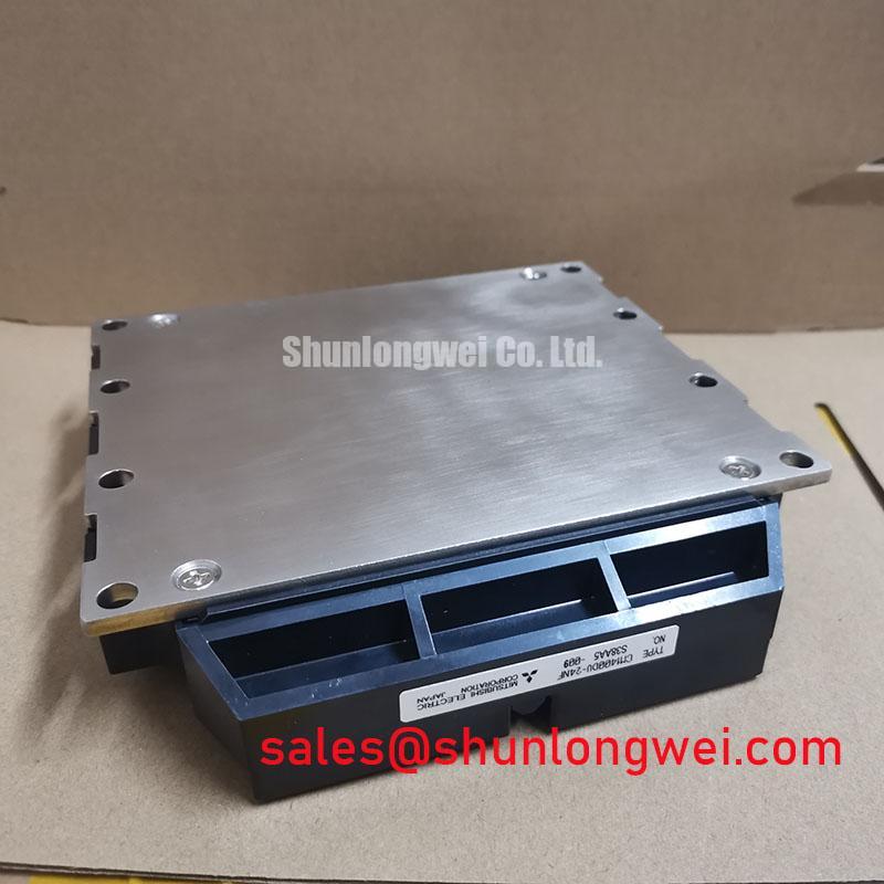
CM1400DU-24NF Mitsubishi IGBT Module Technical Analysis
The CM1400DU-24NF is a high-power dual IGBT module offering a rugged 1200V blocking voltage and 1400A continuous collector current. Utilizing carrier stored trench-gate bipolar transistor technology, this module minimizes conduction losses while delivering an exceptional thermal resistance of 0.032 K/W. Designed for high-frequency switching, it eases design constraints by simplifying parallel layouts and enhancing overall energy efficiency. For high-power UPS applications requiring maximum thermal margins, this 1200V, 1400A module stands as the optimal high-capacity solution.
Key Parameter Overview
Decoding the Specs for Enhanced Thermal Reliability
| Functional Group | Parameter Symbol | Key Metric Specification | Engineering Significance |
|---|---|---|---|
| Maximum Ratings (Tj = 25°C) | VCES | 1200V | Ensures robust voltage blocking in 400V AC industrial lines. |
| IC | 1400A | Handles extreme continuous load currents in heavy industrial drives. | |
| PC | 3900W | Maximum power dissipation limit to prevent safe operating area violations. | |
| Viso | 2500V | Provides strong electrical isolation between terminals and baseplate. | |
| Electrical Characteristics | VCE(sat) (Typ.) | 1.8V | Minimizes conduction losses during high-amperage operation. |
| VGE(th) | 6.0V - 8.0V | Guarantees stable gate control and noise margin during transitions. | |
| Thermal Characteristics | Rth(j-c)Q (IGBT) | 0.032 K/W | Achieves rapid heat transfer from the active switch to the case. |
| Rth(j-c)R (Diode) | 0.053 K/W | Enables reliable cooling for the anti-parallel free-wheel diode. | |
| Rth(c-f) | 0.016 K/W | Reflects the contact thermal efficiency when using standard grease. |
Download the CM1400DU-24NF datasheet for detailed specifications and performance curves.
Application Scenarios & Value
Achieving System-Level Benefits in High-Power Industrial Conversion
Engineers often face massive startup transients when designing heavy conveyor drives or megawatt-class motor control platforms. To solve this issue, the CM1400DU-24NF offers a peak collector current rating of 2800A, allowing systems to safely absorb startup transients without triggering desaturation.
In addition to industrial motor drives, this power module serves as the core switching topology in high-capacity uninterruptible power supplies (UPS) and grid-tie solar inverters. The integration of high-performance internal diodes ensures low reverse-recovery behavior, which directly translates to cleaner output waves and simpler filters. Our ultimate guide to IGBT modules details how these switching dynamics impact total harmonic distortion in industrial power grids.
While this module is perfect for standard 1200V lines, for systems demanding higher voltage margins, the related CM1000DU-34NF provides a VCES of 1700V. Conversely, for lower current requirements, the CM600DX-24T serves as an alternative to downscale the inverter stage.
Technical Deep Dive
Optimizing Carrier Storage for Ultra-Low Saturation Voltage
The outstanding efficiency of this module stems from its Carrier Stored Trench-gate Bipolar Transistor (CSTBT™) technology. Traditional trench designs suffer from high carrier concentration drop-offs near the emitter, which increases forward drop. CSTBT™ addresses this by trapping holes in a buried carrier-storage layer, boosting carrier density uniformly.
What is the primary benefit of the CSTBT architecture? It minimizes saturation voltage to reduce conduction losses.
By engineering this carrier distribution, the device achieves a typical VCE(sat) of only 1.8V. Think of VCE(sat) as a narrow, well-designed toll booth on a busy highway. Instead of stopping traffic and causing excessive heat, the 1.8V saturation voltage acts like an electronic pass, allowing a massive 1400A current to flow through with minimal resistance.
To handle the immense heat generated under full loads, the device incorporates an advanced aluminum nitride isolation substrate. This material reduces the junction-to-case thermal resistance to 0.032 K/W. The thermal resistance is like a wide, multi-lane highway for heat. Heat travels from the silicon die to the copper baseplate as easily as water flowing through a giant industrial spillway, preventing any localized hotspots.
Engineers seeking further design insights can review our guide on IGBT thermal design to understand how case temperatures scale with duty cycles. The internal chip spacing is optimized to allow even heat spreading across the module footprint, ensuring mechanical stability under thermal cycles. This thermal integrity matches the high-quality standards set by Mitsubishi in high-reliability power semiconductors.
Frequently Asked Questions
Engineering Insights and Practical Design Guidelines
How does the low thermal resistance of 0.032 K/W impact heatsink selection?
This ultra-low thermal resistance allows engineers to design much smaller, lightweight heatsinks. It ensures that heat is rapidly moved out of the silicon junction. Consequently, the temperature difference between the junction and the case remains small, which improves long-term module lifespan under heavy, cyclic loads.
Can the CM1400DU-24NF handle continuous linear mode operation?
No, this module is strictly engineered for high-speed switching applications. Operating in the linear region raises the amplification rate and triggers high internal oscillations. Gate voltages must transition rapidly through the 3V to 11V range to avoid thermal runaways or gate destruction.
Is linear operation recommended for this module? No, operating in the linear region causes high oscillation risks.
Ready to optimize your next high-power converter design? Contact our engineering team for current stock availability and technical consulting.