Content last revised on August 28, 2026
CM300DU-12NFH: Optimized High-Frequency Power Conversion
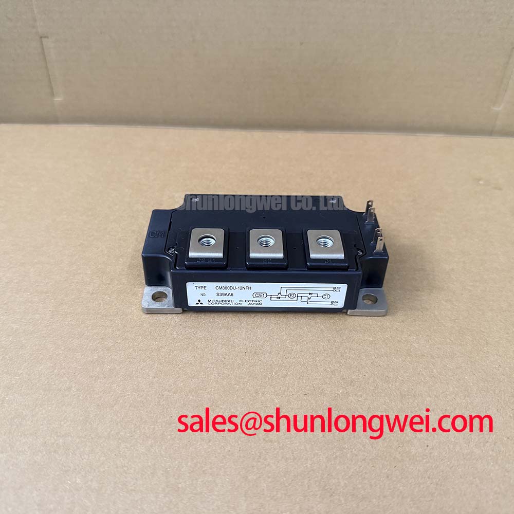
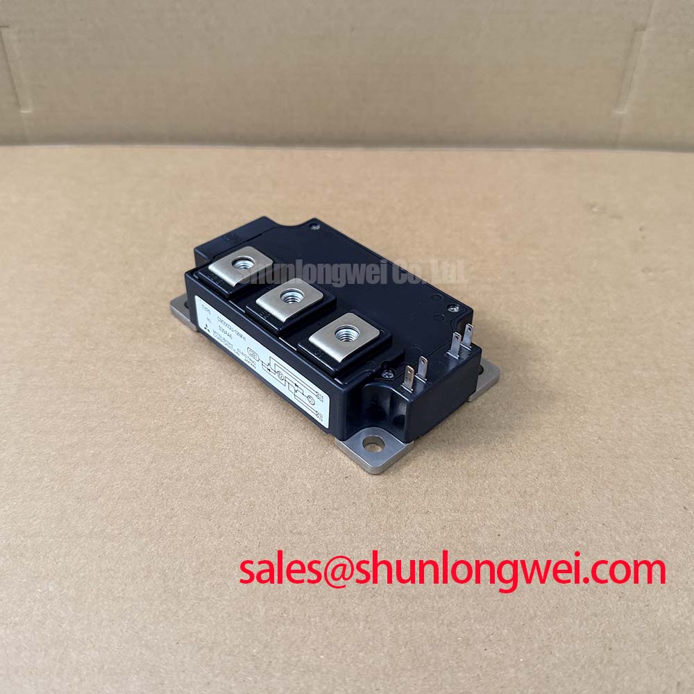
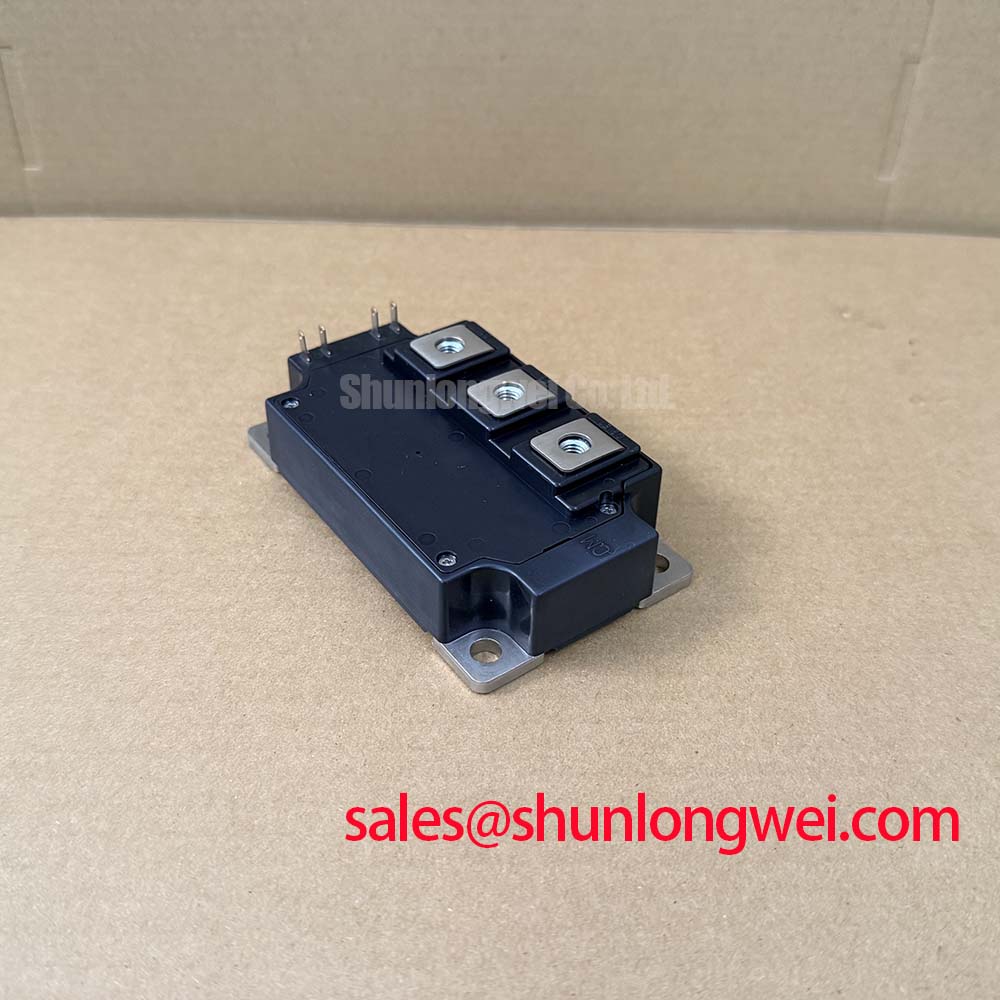
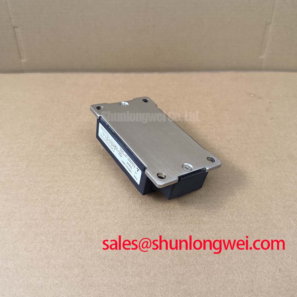
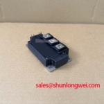
The CM300DU-12NFH, manufactured by Mitsubishi Electric, is a dual half-bridge IGBT module designed for applications demanding rapid switching frequencies. Rated at 600V and 300A with a junction-to-case thermal resistance of 0.16 K/W, it reduces dynamic losses and simplifies thermal layouts. By implementing a highly optimized gate structure, it addresses the technical challenge of switching losses in high-frequency converters. For high-frequency power converters prioritizing switching efficiency at 600V, this 300A module is the optimal choice.
Application Scenarios & Value
Achieving System-Level Benefits in High-Frequency Power Conversion
Engineers often face severe thermal and efficiency bottlenecks when operating traditional IGBT modules at switching frequencies above 20 kHz. In high-power induction heating systems and gradient amplifiers, switching transients generate rapid heat accumulation that threatens device reliability. The CM300DU-12NFH mitigates this by enabling stable operation in the 30 kHz to 60 kHz range, which is critical for maintaining efficiency in resonance-based switching topologies. By limiting gate charge and transient times, the module allows designers to scale down the physical size of magnetic components and passive filters, aligning with industrial standards like IEC 61800-3 for electromagnetic compatibility.
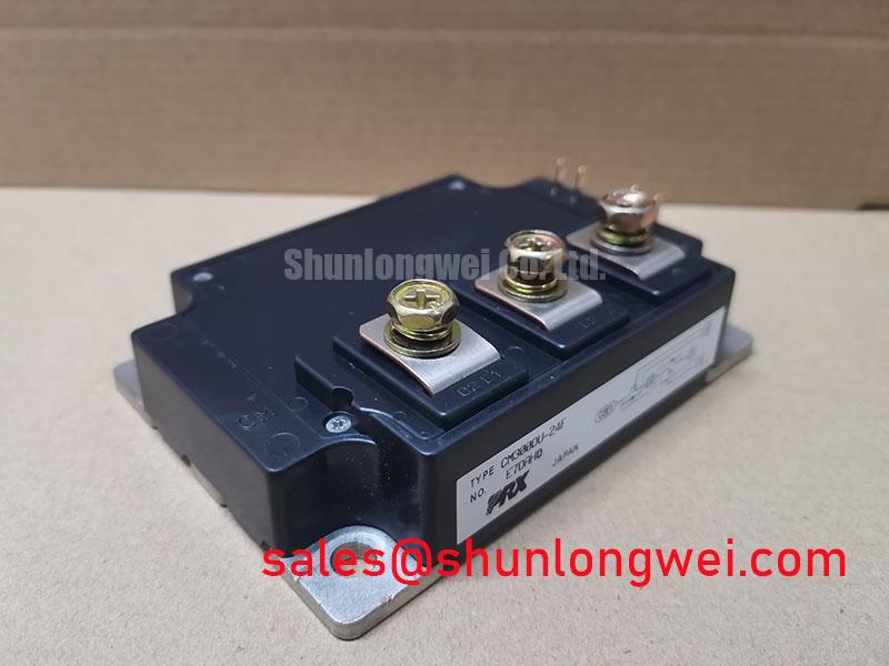
For alternative designs, context is key. While this module is optimal for 600V applications, systems operating on higher input voltages may require the related CM300DU-24NFH, which provides a 1200V collector-emitter rating. Conversely, for designs that do not operate in high-frequency regimes, the standard CM300DY-12NF serves as a baseline offering for standard industrial drives.
Technical & Design Deep Dive
A Closer Look at the Low-Loss Trench CSTBT Structure
The internal architecture of the CM300DU-12NFH utilizes advanced carrier stored trench-gate bipolar transistor technology, which reduces collector-emitter saturation voltage (typically 2.0V at 300A) without compromising turn-off speed. In high-frequency topologies, minimizing the gate charge (typically 1860 nC) is vital. The low gate charge behaves like a lightweight, low-inertia actuator, requiring minimal drive power to toggle state, akin to a precision relay with a highly responsive return spring. This allows the drive circuit to supply less current during switching transitions, lowering overall auxiliary power consumption.
Furthermore, managing the thermal energy dissipated during these rapid cycles is handled by the module's copper base plate. The low junction-to-case thermal resistance (0.16 K/W for the IGBT) acts like a superhighway for heat dissipation, ensuring that thermal energy generated at the silicon junction is evacuated to the base plate almost instantaneously, similar to how a copper thermal bridge rapidly pulls heat away from a high-power microprocessor. This ensures the junction temperature remains safely below the maximum rated 150°C under continuous operation.
Refer to the in-depth analysis of IGBT modules for a comprehensive understanding of how gate layout influences switching dynamics. For design layout strategies, engineers can consult the guide on IGBT design and integration to optimize gate drive loops. And for a comparative view of different devices, our power semiconductor selection guide outlines standard testing protocols.
Key Parameter Overview
Decoding the Specs for Enhanced Thermal Reliability
| Parameter | Typical/Maximum Value | Engineering Significance |
|---|---|---|
| Collector-Emitter Voltage (VCES) | 600V | Defines the maximum voltage limit across collector-emitter with gate-emitter shorted. |
| Collector Current (IC) | 300A | Continuous DC current handling capability at controlled case temperatures. |
| Collector-Emitter Saturation Voltage (VCE(sat)) | 2.0V (Typical at Tj=25°C) | Determines conduction losses during the on-state. |
| Thermal Resistance (Rth(j-c)Q) | 0.16 K/W (Maximum per IGBT) | Defines thermal dissipation efficiency from the silicon junction to the case. |
| Gate-Emitter Voltage (VGES) | ±20V | Safe operating range for the control gate drive circuit. |
| Isolation Voltage (Visol) | 2500 Vrms | Ensures electric isolation between active components and the copper base plate. |
Download the CM300DU-12NFH datasheet for detailed specifications and performance curves.
Frequently Asked Questions
Engineering Queries for High-Frequency Integrations
What is the primary switching frequency range of this module?
It is optimized for high-frequency switching between 30 kHz and 60 kHz.
What is the thermal resistance limit for each IGBT switch?
The junction-to-case thermal resistance is rated at a maximum of 0.16 K/W.
Is a negative gate voltage required to turn off the CM300DU-12NFH reliably in high-frequency applications?
Yes, applying a negative gate-emitter voltage (typically -15V) is recommended. This setup prevents parasitic turn-on caused by high dv/dt transients across the Miller capacitance during fast switching transitions.
Implementing the CM300DU-12NFH aligns with modern industrial drives toward high power density and energy conservation compliance. Selecting the correct gate drive parameters and thermal interfaces ensures that power conversion stages achieve optimal performance and long-term operating life in demanding industrial environments.