


Content last revised on September 29, 2026
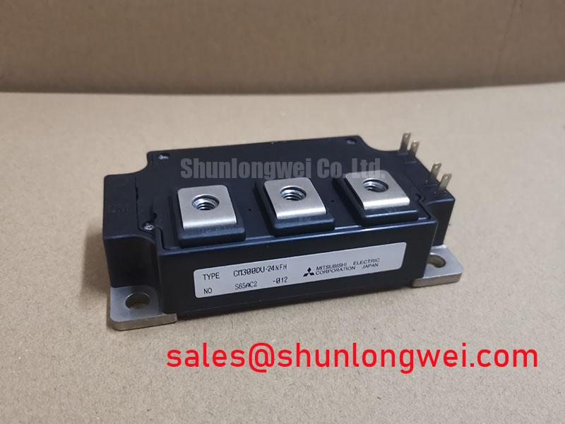
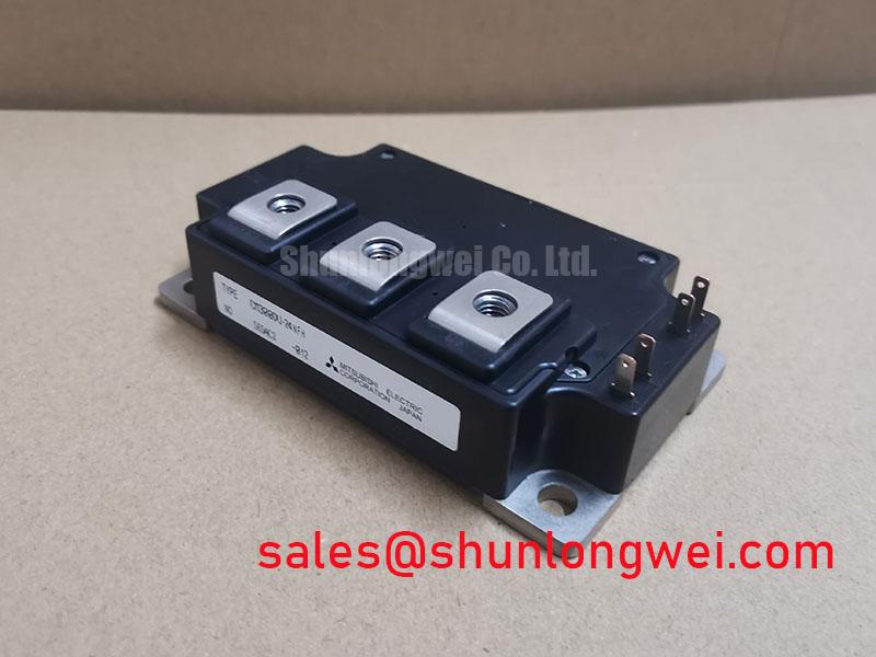
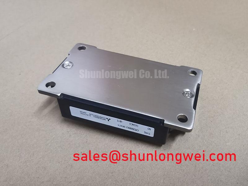
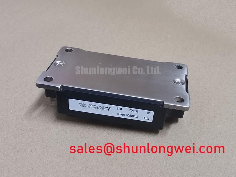
Assembly Integrity and Heatsink Contact for CM300DU-24NFH
Check the heatsink contact pattern when a replaced CM300DU-24NFH develops an unexpected temperature rise under load. Remove power, allow the DC link to discharge under the equipment’s service procedure, and inspect the mating surfaces for old thermal compound, raised burrs and contamination. An uneven imprint can indicate poor contact; it does not, by itself, identify whether the module, heatsink or mounting process is responsible.
The module’s 1200 V and 300 A ratings are Official Specifications, not a promise that an existing cooling assembly can carry every duty cycle at that current. As a Design Consideration, apply thermal interface material as a thin, continuous layer that fills surface irregularities without leaving visible voids or a heavy excess. Baseplate curvature and heatsink flatness affect how that layer spreads. Verify both against the applicable assembly drawings rather than assuming a visually flat surface will make uniform contact.
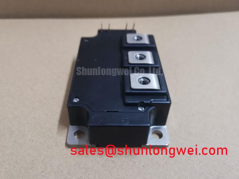
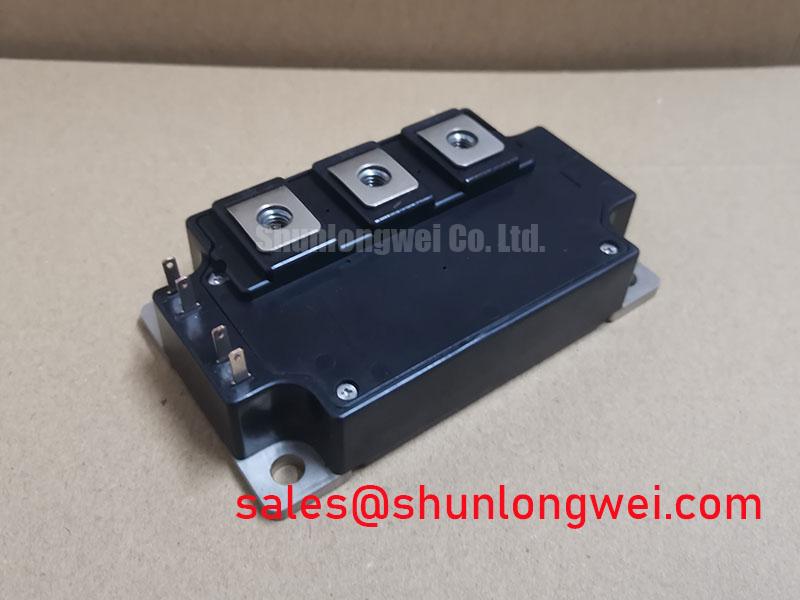
Seat the module evenly and tighten its mounting screws in the sequence and to the torque specified for the assembly. Do not substitute a generic fastener torque for a module mounting requirement that has not been established for this installation. Keep the power terminals free of mechanical strain from the busbar: a rigid connection that pulls the housing out of position can undermine an otherwise careful thermal installation. Confirm electrical clearance around the terminals against the equipment layout and the applicable insulation requirements.
Maintenance note: Recheck terminal tightness using the approved service procedure and investigate rising contact temperature alongside heatsink cleanliness and airflow.
For preventive maintenance, compare temperature trends at similar load and ambient conditions rather than judging one reading in isolation. Inspect the heatsink air path for dust and check whether thermal compound has dried or migrated during service. Where equipment moves between cold and humid conditions, look for condensation before energizing the assembly; moisture management belongs to the enclosure and operating procedure, not to an assumed property of the module.
Gate Drive and Hard-Switching Checks for CM300DU-24NFH
Capture the gate-to-emitter waveform at the module terminals when switching noise, unexplained trips or asymmetric heating appears after installation. Compare commanded turn-on and turn-off with the measured waveform under the same operating conditions. A clean driver output measured only at the driver board can conceal voltage disturbance along the gate connection. Check the return path, connector seating and routing alongside the waveform.
As a Design Consideration, hard-switching behavior depends on gate-drive impedance, DC-link layout, load current and the equipment’s operating sequence. Tune the drive with switching tests that observe both collector-to-emitter voltage and current. Faster switching may reduce one loss component while increasing overshoot or noise; slower switching may ease a transient while increasing dissipation. The acceptable balance is system-determined and must preserve the module’s electrical and thermal limits. Mitsubishi Electric’s power semiconductor information provides manufacturer context for evaluating power-device behavior, while the equipment’s own drive design governs the actual installation.
If the driver uses a bootstrap supply for a high-side switch, examine its supply voltage during the longest commanded on-time and during rapid switching. As an Engineering Recommendation, capacitor selection should account for the charge delivered to the gate, driver consumption, leakage and the opportunity to recharge. Check the bootstrap diode’s behavior under the actual switching conditions as well. This is a driver-circuit assessment, not a stated CM300DU-24NFH capacitor value or an assumption that every installation uses a bootstrap driver.
Review the protection sequence on the schematic before interpreting a short-circuit trip. Detection delay, blanking, driver supply behavior and turn-off action must be assessed together against the module’s applicable safe-operating information. An abrupt turn-off can aggravate inductive overvoltage, while an excessively delayed response can increase device stress. A staged turn-off is a possible system design approach, but its timing cannot be prescribed from the voltage and current ratings alone. The Precision Gate Drive Design guide is useful background for tracing gate-loop and protection interactions during that assessment.
Busbar Layout, Transient Protection and Replacement Fit
Probe the collector-to-emitter turn-off peak at the module terminals if trips occur during current changes or after busbar work. Measure it with a suitable high-voltage differential probe and a short measurement loop, then compare the observed peak with the DC-link level and the applicable device limit. A trace taken elsewhere in the cabinet can miss voltage developed across the connection between the probe point and the module.
As a Design Consideration, the turn-off peak rises with DC-link voltage and the voltage induced by stray inductance as current changes. Closely coupled, symmetrical outgoing and return paths can reduce loop inductance, but no universal busbar-inductance target follows from this module’s 1200 V rating. The layout engineer should check the worst observed switching condition and confirm voltage margin in the assembled equipment. Snubber choice likewise depends on measured ringing, energy, placement and the operating cycle; selecting a capacitor by current rating alone is not sufficient.
When inspecting a planar busbar, look for changes introduced by service work: displaced spacers, altered connection order, loose joints or a replacement link with a different current path. Keep the busbar mechanically supported so terminal forces do not disturb the module mounting. Check the completed layout for required clearance and creepage under the equipment’s insulation design. Neither the package description nor the voltage rating establishes a blanket clearance rule for every enclosure.
For replacement screening, compare the original unit’s circuit drawing, terminal arrangement, mounting footprint, cooling interface and gate-drive requirements with the candidate hardware. The CM35MXA-24S is a separate Mitsubishi Electric model worth examining in a cross-model comparison, not a confirmed drop-in replacement for CM300DU-24NFH. Its fit must be established from the relevant specifications and the equipment schematic before any substitution decision. Mitsubishi Electric’s semiconductor device information offers manufacturer-level reference material for that broader device review.
Output Filter Diagnosis in Inverter Equipment
Measure voltage at the inverter output and at the far end of a long motor lead when terminal stress or nuisance trips appear after a cable change. Compare the waveforms under the same operating state. A pronounced difference may point to a cable-and-load reflection problem, but probe placement, grounding and the drive’s switching pattern must be checked before assigning a cause to the waveform.
As a Design Consideration, an output dv/dt reactor and a sinusoidal filter address different system needs. A reactor can moderate edge rate, whereas a sinusoidal filter is intended to shape the output waveform more extensively. Either choice requires evaluation of cable length, load characteristics, switching behavior, filter losses and the drive manufacturer’s permitted operating range. The CM300DU-24NFH rating does not determine filter size or establish that a filter is required.
An industrial inverter welder or a medium-frequency induction-heating supply may be a candidate for evaluation where its schematic, thermal design and switching duty match the module. Those applications should not be treated as proof of compatibility. In particular, inspect the actual output topology before applying motor-lead filter guidance to either machine: a welder transformer connection and an induction-heating load can present different electrical conditions from a long motor cable.
After an output-network change, repeat the module-terminal switching measurements and monitor heatsink and connection temperatures at representative load. A filter that improves a remote voltage waveform can still change current, losses or protection behavior at the inverter. Record the before-and-after waveforms with operating conditions so the equipment team can distinguish a genuine improvement from a change in test setup.