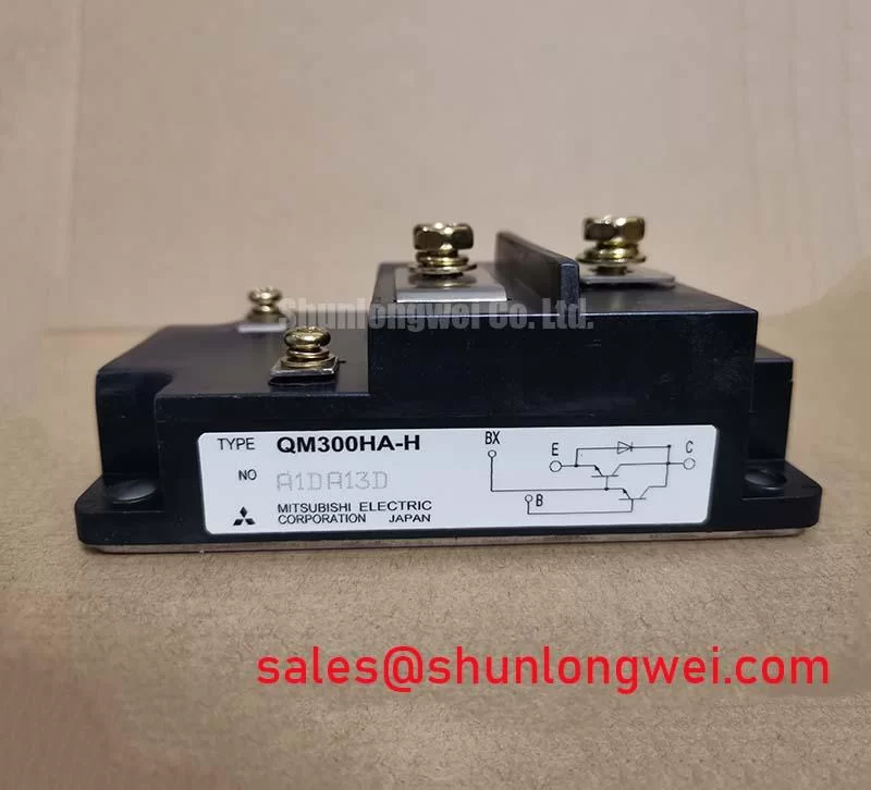


Content last revised on September 10, 2026
QM300HA-H Circuit Protection & Reliability: Calibrating High Frequency Commutation Loop Inductance
| Parameter | Official Specification |
|---|---|
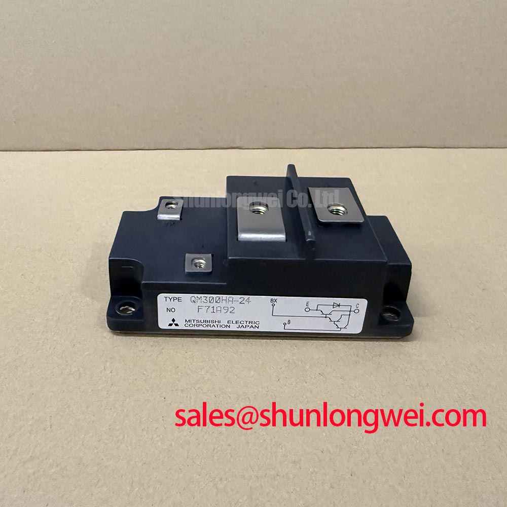
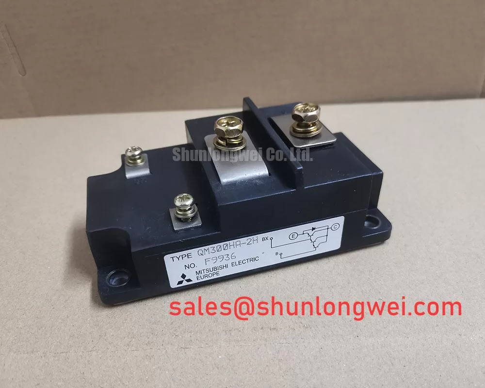
| Model | QM300HA-H |
| Manufacturer | Mitsubishi Electric |
| Product Category | Power Transistor / Darlington Module |
| Collector Emitter Breakdown Voltage | 600.0 V |
| Continuous Collector Current | 300.0 A |
| Module Enclosure Configuration | Module with isolated baseplate |
| Target Operating Topologies | Industrial power conditioning, inverters, and multistage conversion |
Probe the switching node and DC link with a properly rated oscilloscope before changing the power module, then compare the measured turn off overshoot with the inverter’s documented voltage boundary. A transient that exceeds the expected switching envelope can originate from commutation loop inductance, busbar asymmetry, unsuitable clamping, or measurement probe placement rather than from the QM300HA-H itself.
The QM300HA-H is specified for a 600.0 V collector emitter breakdown voltage and a 300.0 A continuous collector current. These are official device specifications, not recommended operating targets for every inverter. The actual switching voltage, current, temperature, pulse duration, and cooling conditions remain system determined. Designers should verify the complete operating point against the original Mitsubishi Electric technical documentation and the converter’s protection settings.
During a commutation test, use a short measurement loop and confirm that the probe ground arrangement is not adding an artificial spike. Record the DC link voltage, collector emitter waveform, base signal, and load current at the same time. The relationship between peak voltage, DC link voltage, stray inductance, and current slew rate can be treated as an engineering calculation: peak stress rises as parasitic inductance and current transition speed increase. This makes physical loop control more reliable than attempting to correct every overshoot through software timing alone.
A symmetrical planar busbar arrangement is a practical design consideration for commercial string inverter and micro grid storage equipment. Keep the outgoing and returning high current paths physically close, avoid unnecessary loop area, and preserve similar geometry for parallel switching paths. The capacitor and clamping network should be selected from measured transient energy, switching conditions, and the semiconductor protection strategy. Exact snubber capacitance, clamp voltage, and layout clearance must be established by the system designer through switching tests rather than assigned as universal values for this module.
Inspect the isolated baseplate for mounting distortion, contamination, and uneven contact with the heatsink. Thermal interface coverage should be continuous and thin, while the mechanical fasteners should follow the applicable screw specification and the equipment manufacturer’s torque process. Poor mechanical contact can increase junction temperature and may change the waveform during repeated load transitions.
For a repair comparison, the QM200HA-HK can be evaluated as a related component, but its electrical ratings, terminal arrangement, base-drive requirements, and mechanical outline must be checked independently before any substitution decision. Similar housing appearance does not establish circuit compatibility.
QM300HA-H Circuit Protection & Reliability: Calibrating Differential Base-Emitter Loop Routing to Suppress Oscillation
Measure the base to emitter waveform directly at the module terminals while observing the collector current transition; do not diagnose base-drive instability from the driver board test point alone. A clean signal at the driver may become distorted at the power terminals because of shared emitter impedance, unequal trace lengths, connector inductance, or coupling from the main current path.
Base loop routing is a design consideration that should separate the base-drive return from the high current emitter route wherever the module and driver topology provide an auxiliary return connection. The objective is to reduce mutual coupling and prevent the voltage developed by high di/dt current from appearing in the base reference. Designers should keep the forward and return base-drive paths close together, maintain equivalent routing for parallel devices, and verify propagation delay and ringing at the actual module terminals.
The QM300HA-H product information supplied for this page confirms the module enclosure and isolated baseplate configuration, but it does not provide a complete terminal map, base-drive specification, internal base resistance, or auxiliary emitter definition. Those details must be taken from the original Mitsubishi Electric documentation for the exact production version. The system integrator should not infer pin functions from a visually similar power transistor module.
When a converter shows intermittent overcurrent trips during rapid load changes, compare the base waveform from a known good phase with the affected phase. Check turn on and turn off timing, negative excursions, ringing, dead time, and the relationship between base voltage and collector current. A distorted waveform may indicate impedance mismatch or unwanted coupling; verify the signal path, driver supply integrity, isolation barrier behavior, and module terminal connections before replacing the power device.
High speed semiconductor fuse coordination is another engineering recommendation for high energy converter assemblies. The fuse clearing characteristic, system fault current, module short circuit withstand capability, DC link energy, and protection response must be evaluated together. Fuse I²t coordination cannot be established from the continuous collector current rating alone. The final protection design should be validated with controlled fault testing and suitable equipment protection procedures.
⚠️ Field Alert: Isolate and discharge the DC link before disconnecting base-drive or power terminals, because residual energy can damage the driver and create a serious service hazard.
QM300HA-H Circuit Protection & Reliability: Calibrating Fault Clearing Dynamics: Type I and Type II Desaturation
Capture the base signal, collector emitter voltage, and fault current during a controlled protection test to determine whether the desaturation circuit detects the event quickly and turns the device off without creating excessive inductive stress. A protection trip alone does not prove that the detection threshold, blanking interval, clamp behavior, and turn off profile are correctly coordinated.
Type I and Type II desaturation protection are system level methods for detecting abnormal collector emitter voltage during conduction. The protection circuit typically needs a controlled blanking period to avoid reacting to the normal voltage transition at turn on, followed by a fault decision when the device remains outside the expected conduction condition. The supplied official data for the QM300HA-H does not specify a universal desaturation response time or short circuit safe operating area. Any claimed microsecond limit must therefore come from the exact manufacturer datasheet or an authoritative application document, not from the continuous current rating.
A two stage soft turn off sequence may be considered when the power stage and driver support it. The first stage limits the current transition to reduce inductive voltage rise; the second stage completes turn off after the fault energy has been controlled. The correct base resistance, clamp level, delay, and fault latch behavior depend on the driver, busbar, DC link, load, and protection architecture. Engineers should verify the collector emitter peak against the module voltage rating during representative fault tests.
Field troubleshooting should begin with the desaturation diode path, blanking capacitor, base driver supply, isolation components, and fault feedback line. Inspect for contamination or damaged insulation around high voltage sensing points. A false trip may result from switching noise, poor return routing, incorrect threshold selection, or a real abnormal conduction event. Conversely, the absence of a trip does not establish safe operation if the sensing path is open or incorrectly referenced.
The isolated baseplate is useful for mechanical and thermal integration, but isolation performance in the finished equipment depends on mounting surfaces, contamination, creepage, clearance, fasteners, thermal materials, and enclosure conditions. The module should not be described as independently certified for the complete inverter’s EMC, insulation, or safety compliance. For manufacturer technical references, engineers can consult Mitsubishi Electric Power Semiconductors & High Power Modules and Mitsubishi Electric Global Semiconductor Device Technologies.
Preventing Spurious Faults: Derating Guidelines and Mismatched Parameter Guidelines for QM300HA-H
Check each phase for equal base-drive timing, comparable collector current, consistent thermal contact, and the same busbar geometry before attributing a spurious fault to the QM300HA-H. Phase comparison is particularly valuable in commercial string inverters and energy storage converters, where one abnormal waveform can be hidden by an averaged controller measurement.
The official continuous collector current rating is 300.0 A, while the official collector emitter breakdown voltage is 600.0 V. These values define important device boundaries, but they do not replace thermal, switching, pulse, short circuit, or repetitive fault analysis. Current derating should be established from the heatsink capability, ambient conditions, switching frequency, duty cycle, transient load profile, and allowable junction temperature specified for the exact device.
Static current sharing between parallel power devices can benefit from the positive temperature behavior often associated with the on state voltage of semiconductor switches, but dynamic sharing is governed by base-drive loop impedance, propagation delay, stray inductance, and physical layout. This is a design consideration, not a guaranteed sharing characteristic for an unspecified parallel arrangement. Match the electrical path lengths and confirm current distribution with isolated probes or suitable current sensors during switching tests.
Parameter mismatch checks should include voltage class, continuous and pulsed current capability, terminal arrangement, base-drive requirements, thermal interface dimensions, isolation construction, and protection compatibility. The product category supplied for this listing is Power Transistor / Darlington Module; engineers should verify whether the existing converter requires a particular internal topology or switching characteristic before approving a replacement. A module with a similar current label may still be unsuitable if its dynamic or mechanical parameters differ.
In a multistage conversion system, the preceding rectifier and the switching stage should be evaluated as one protection chain. The QM100HY-2H may be considered as a related rectifier or complementary stage component, subject to independent verification of ratings, terminal definitions, thermal requirements, and circuit function.
For base-drive reliability, the technical guide Evolution of Negative Off Bias Gate Drive Circuits concerns gate-controlled devices and should not be treated as a direct guide for the QM300HA-H Darlington module. Base-drive requirements should instead be evaluated from the actual driver architecture, insulation method, switching behavior, and manufacturer requirements for the assembled equipment.
When installing the module in a field repair, record the original busbar orientation, terminal hardware, insulator placement, thermal interface condition, and base wiring before removal. After installation, perform a low energy continuity check, confirm base-drive isolation, inspect the mechanical seating, and bring the converter up through a controlled test sequence while monitoring phase current and switching voltage. These checks help distinguish a wiring or protection mismatch from a device fault without assigning a single cause to an unverified symptom.