

Content last revised on September 19, 2026
LF 305-S/SP11 Thermal-Electrical Optimization: SCSOA Overcurrent Protection: Implementing Practical Tuning
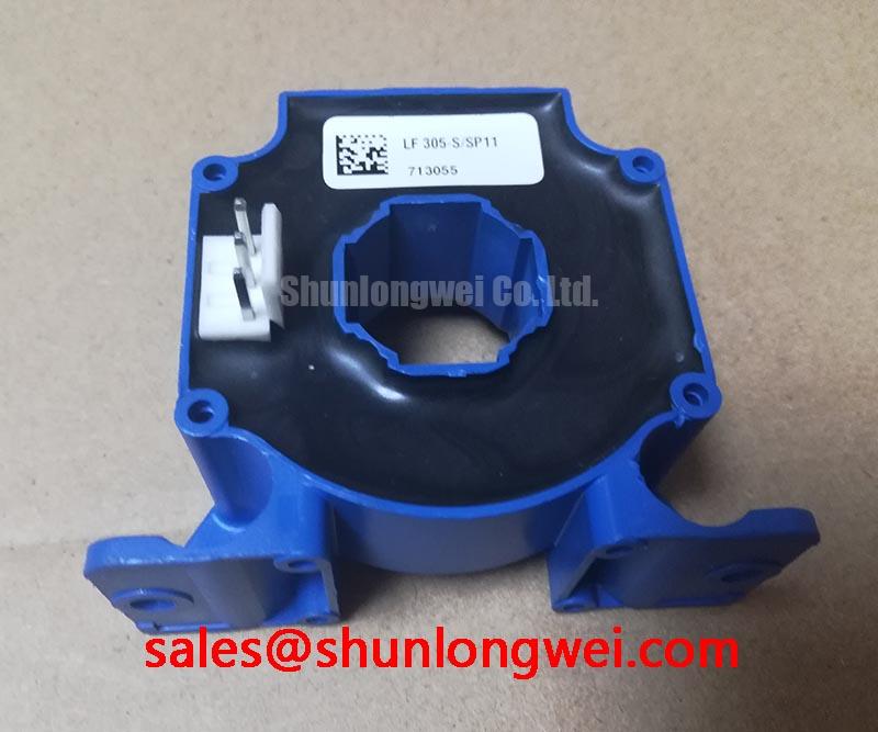
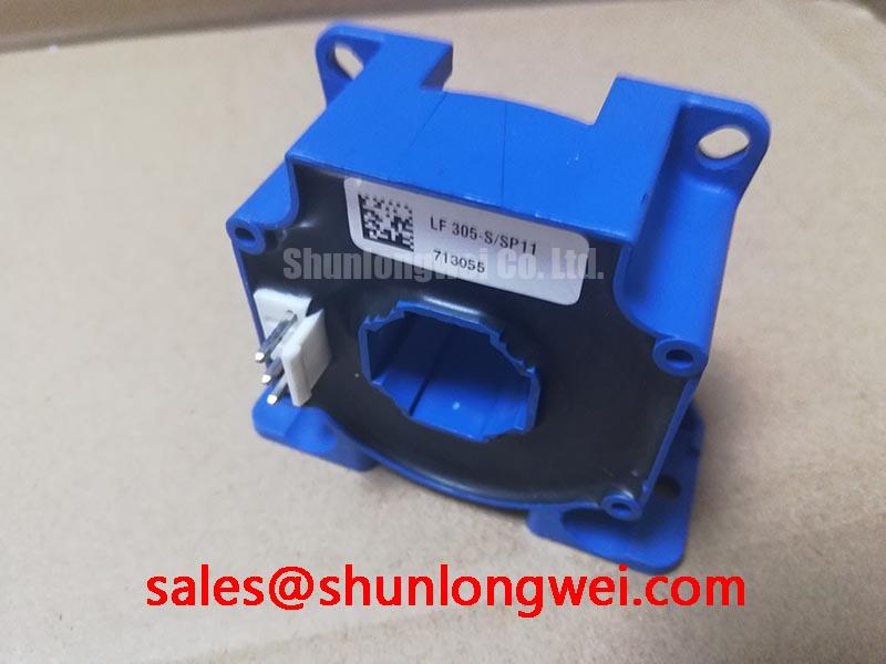
Begin incoming inspection by isolating the LEM LF 305-S/SP11 from the control circuit, recording its label data, checking the closed-loop opening for mechanical obstruction, and comparing the marked terminals with the original equipment documentation. The published product information identifies this device as a 300.0 A closed-loop current transducer. The exact supply, output, terminal polarity, insulation, and installation limits should be verified from the applicable LEM documentation before energizing a replacement.
| Parameter | Published product information | Engineering use |
|---|---|---|
| Manufacturer | LEM | Confirm the system documentation and component marking agree |
| Model | LF 305-S/SP11 | Use the complete suffix when checking compatibility |
| Rated current | 300.0 A | Compare with the monitored conductor and converter operating envelope |
| Construction | Closed-loop transducer | Route the measured conductor through the sensing aperture without mechanical force |
| Supply and insulation requirements | Verify from the applicable LEM documentation | Confirm compatibility with the system supply and insulation requirements |
The transducer is a measurement element in the protection chain, not a substitute for the converter’s short-circuit safe operating area protection. In an industrial inverter welder or medium-frequency induction heating supply, the control board may use measured current to initiate pulse blocking, reduce commanded current, or coordinate a two-stage soft turn-off sequence. The detection threshold, blanking interval, gate-drive response, and switching energy remain system-level design variables. They should be validated with the actual power stage and a known-good waveform rather than inferred from the transducer’s 300.0 A rating.
For regenerative braking choppers and high-power braking resistor banks, verify that the measured-current signal remains credible during the transition between energy absorption and normal operation. A saturated or incorrectly referenced feedback signal can delay protective action, while excessive common-mode disturbance can create an apparent overcurrent event. Check the transducer supply rails at the device terminals, inspect the return path to the controller, and compare the sensor output with a suitably rated independent current measurement during a controlled low-energy test.
A practical protection review should include the complete path from conductor placement through signal conditioning, comparator or ADC processing, PWM shutdown, and gate-driver action. If the system uses desaturation sensing or a separate collector-emitter fault detector, confirm that its timing is coordinated with the current-feedback path. The LF 305-S/SP11 should be evaluated as one input to that protection architecture, not as evidence that a particular short-circuit response time is guaranteed.
Preventing Spurious Faults: Optimizing Gate Drive Loop Geometry for the LF 305-S/SP11
Although the LF 305-S/SP11 measures current rather than controlling a gate directly, its signal integrity depends on the physical relationship between the high-current power loop, the sensor aperture, and the control wiring. Keep the transducer output wiring away from fast-switching power conductors where practical, and route the signal return to the intended controller reference rather than allowing it to share a high-current return path. The final arrangement should be checked under switching conditions, because a quiet resistance measurement cannot reveal common-mode ground bounce or capacitive coupling.
When the sensor is installed in an inverter welder, inspect the conductor position through the closed loop and document its orientation before removal. A reversed conductor direction can produce an inverted feedback signal even when the supply connections are correct. Do not assume terminal polarity from a visually similar unit; use the original wiring record and the relevant LEM documentation. With power removed, check for unintended continuity between the sensor signal terminals, shield, chassis, and nearby power conductors according to the approved service procedure.
The gate-drive loop itself should be compact and separated from the main high-current emitter or source path where the power semiconductor arrangement provides a dedicated control return. This is a general design consideration for reducing mutual coupling and oscillation; it is not a published electrical specification of the LF 305-S/SP11. The desaturation or short-circuit protection timing should be selected by the power-stage designer after measuring the actual switching waveform, device response, propagation delay, and fault energy.
Use an oscilloscope with suitable isolation and bandwidth practices to compare the transducer output, controller threshold, PWM command, and gate-driver response. A fault that appears only during switching may indicate impedance interaction, reference movement, or measurement pickup rather than a defective transducer. Compare the waveform with the known-good signal path, inspect connector seating, and verify the supply at the sensor terminals while the converter is in a controlled operating state.
For a neutral replacement assessment, the DWM100X2-12U may be reviewed as a separate current-sensing option, but interchangeability must be established from current range, aperture, supply, output behavior, mechanical fit, insulation requirements, and controller scaling. A similar current rating alone does not establish a direct replacement.
Benchtop Waveform Tuning: Mitigating Stress via DC-Link Capacitance Bank Layout and Low-ESR Design on the LF 305-S/SP11
Before applying switching power, inspect the DC-link capacitor bank, bus connections, discharge circuit, and sensing harness. A current transducer cannot correct voltage overshoot created by stray inductance in the commutation loop. The engineering relationship is straightforward: the additional turn-off voltage rises with loop inductance and current slew rate, so the system designer must minimize the high-current loop and verify the measured peak against the converter’s permitted voltage boundary.
Use short, broad, and symmetrical bus connections where the topology permits, while keeping the control and sensor wiring physically separated from the switching node. The capacitor bank should be positioned according to the power-stage commutation path rather than simply placed near the enclosure wall. Any snubber or clamp network requires validation at the actual operating current and switching condition; its capacitance, resistance, pulse capability, and thermal behavior are system-design choices, not specifications of the LF 305-S/SP11.
Low equivalent series impedance in the DC-link network can reduce local voltage disturbance, but it can also change ringing behavior and circulating current. During bench tuning, record the current-feedback signal at the transducer output together with the DC-link voltage and switching waveform. If the sensor signal contains a narrow disturbance that is absent from an independent current probe, inspect shielding, reference routing, probe placement, and controller input filtering before changing the protection threshold.
In medium-frequency induction heating equipment, the relationship between the resonant load, inverter bridge, DC-link bank, and current-feedback loop can be particularly sensitive to wiring changes. The system integrator should verify the required sensor bandwidth, output scaling, supply conditions, and control-loop stability from the original equipment design. A Bode plot review can help assess gain and phase margin in the surrounding power-supply or signal-conditioning loop; see Bode Plot Frequency Response and Gain/Phase Margin in Power Supplies.
Where a braking chopper feeds a large resistor bank, confirm that the current-feedback signal is correctly scaled during both transient energy absorption and steady conduction. The resistor bank, switching device, clamp, and thermal monitoring must be evaluated as a coordinated assembly. The LF 305-S/SP11 provides the specified current-transducer function, while the allowable transient profile depends on the converter, wiring, control algorithm, and cooling system.
Field Diagnostics & Commissioning: Symmetrical Busbar Geometry for High-Current LF 305-S/SP11 Topologies
Commissioning should start with a cold-state record. With the equipment isolated and discharged, inspect the sensor body, connector, mounting position, conductor centering, and cable strain relief. Use the approved resistance and diode-test procedure only on terminals that the original documentation identifies for that purpose; do not apply a meter test voltage across unknown supply or output terminals. A generic diode-mode reading is not a universal acceptance value for this transducer, so compare results with a documented known-good unit or the manufacturer’s specified test method.
Check the output polarity by applying a controlled, low-risk current in the documented conductor direction and observing whether the signal moves in the expected direction. The test current must remain within the calibrated test arrangement and equipment safety limits. If the reading is implausible, check the conductor orientation, sensor supply, controller reference, scaling configuration, connector contacts, and oscilloscope reference before attributing the issue to the transducer.
Symmetrical busbar geometry is relevant when several semiconductor paths share current. Equal electrical path length, comparable conductor impedance, and matched gate-drive routing can improve dynamic balance, but the final result must be confirmed by measuring each branch under the intended load. Static current sharing may also vary with semiconductor temperature and device characteristics. Do not infer balanced current from a single controller signal or from the LF 305-S/SP11’s 300.0 A rating.
For mechanical installation, ensure that the monitored conductor does not impose side loading on the closed-loop body and that the mounting arrangement remains secure during thermal cycling and vibration. Bench Tip: Use ESD protection, record the cold-state baseline before connection, and disconnect power before inserting or removing the transducer harness.
When the sensor is part of a rectifier, inverter, or braking topology, review the upstream and downstream protection together. The MBM200H45E2-H can be considered as a neutral reference for a related rectifier-stage evaluation, subject to the actual circuit documentation and electrical compatibility review. For gate-drive and switching-loop coordination, the Precision Gate Drive Design guide provides additional engineering context without replacing the original equipment validation procedure.
After commissioning, compare the LF 305-S/SP11 output with the controller’s displayed current, the expected conductor direction, and an independent measurement during a controlled load increase. Investigate disagreement by tracing the signal from the transducer terminals to the control input, checking supply stability and reference integrity at each point. This approach separates sensor installation, wiring, signal-conditioning, and power-stage behavior without assigning a single cause before the evidence is measured.