
Content last revised on September 10, 2026
Preventing Spurious Faults: Thermal Paste Degradation Prevention and Mounting Guidelines for 5SNE0800E330100
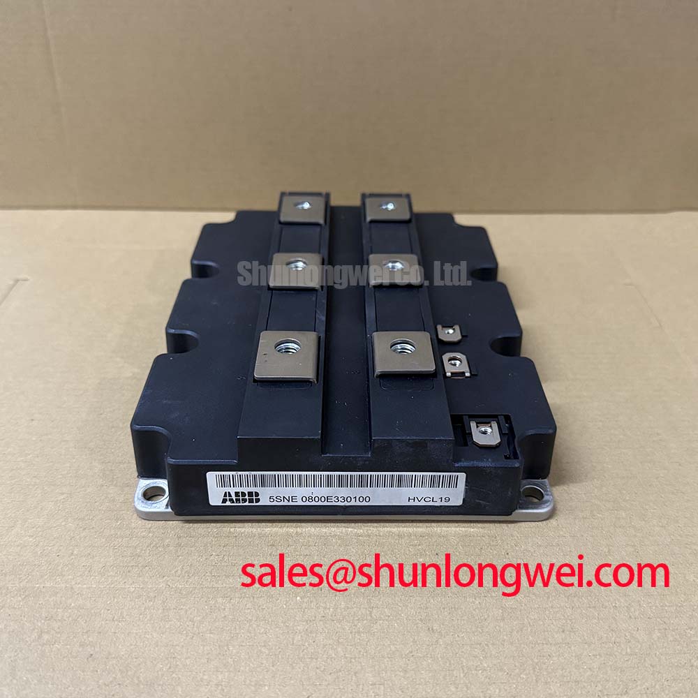
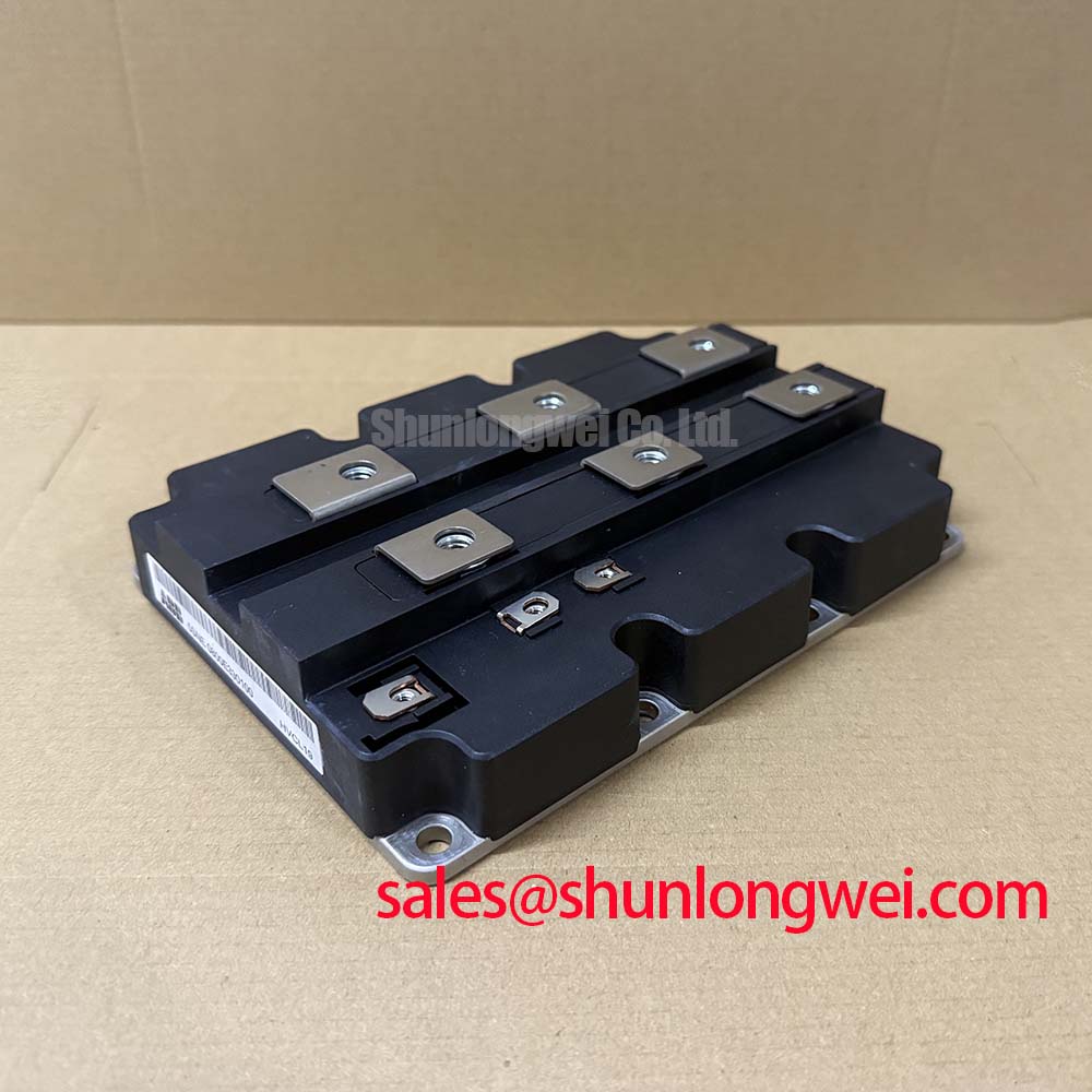
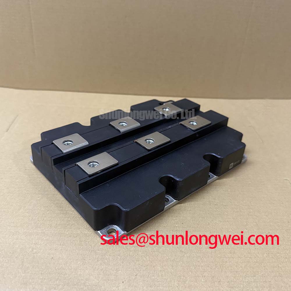
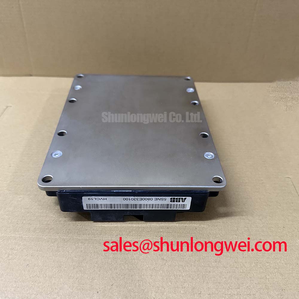
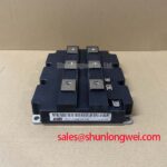
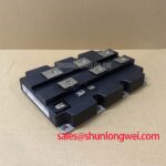
Before installation, verify the nameplate rating, inspect the HiPak2 baseplate for handling damage or contamination, and confirm that the mating drive assembly matches the original power stage topology. The ABB 5SNE0800E330100 is an IGBT module with a specified 3300 V VCES voltage rating and 800 A collector-current rating under the applicable datasheet conditions. Its stated 6000 V isolation voltage, 150°C maximum junction temperature, and established HiPak2 mechanical format make these values central checkpoints when evaluating a replacement power position in a high voltage converter.
| Technical parameter | Official specification | Integration relevance |
|---|---|---|
| Collector emitter voltage | 3300 V | Defines the blocking voltage class for the converter position. |
| Continuous collector current | 800 A | Establishes the continuous current rating under datasheet conditions. |
| Isolation voltage | 6000 V | Relevant to insulation coordination within high voltage equipment. |
| Maximum junction temperature | 150°C | Defines the published semiconductor temperature boundary. |
| Package | HiPak2 | Supports comparison with the existing mechanical interface and busbar geometry. |
A thermal inspection should begin with the removed module and heatsink as a matched surface pair. Old interface material that has dried, pumped away from the contact area, or collected debris can increase thermal resistance and produce temperature related trips that resemble a semiconductor fault. The 150°C Tjmax figure is an Official Datasheet Specification, not an intended operating target. The system integrator should assess actual junction temperature through the converter’s approved measurement method and verify that cooling performance remains inside the equipment manufacturer’s operating limits.
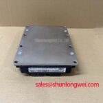
As a Design Consideration, use a controlled thin thermal interface layer, commonly within the general 50 to 100 μm application range when the selected material and mounting process support it. The purpose is to fill microscopic surface irregularities without creating an unnecessarily thick thermal barrier. Inspect the heatsink for flatness, corrosion, embedded particles, and local distortion. Where baseplate curvature or heatsink irregularity is present, the assembly process should be reviewed rather than compensated by excessive paste volume.
Mounting screws should be tightened progressively in a diagonal sequence so clamping pressure develops evenly across the baseplate. The applicable torque, thread condition, washer arrangement, and fastening sequence must be verified against the converter documentation and the mechanical instructions for the installed hardware. Busbars should align without side loading the power terminals. A forced busbar position can create uneven mechanical stress and degrade contact consistency over repeated thermal cycling.
⚠️ Maintenance Note: Periodically monitor terminal contact temperature and verify that heatsink fins, cooling channels, and cabinet airflow paths remain free of dust accumulation.
When a drive shows intermittent thermal alarms, record operating current, coolant or air path condition, heatsink temperature, and gate driver fault status before removing the module. This distinguishes a cooling path concern from a gate drive or load related event and avoids treating one symptom as proof of a single cause. The linked eutectic alloy reference provides useful general background on phase behavior in thermal packaging materials, but it does not define the internal construction of this specific ABB module.
Preventing Spurious Faults: Mitigating Hard Switching Transients via Gate Drive Guidelines for 5SNE0800E330100
Hard switching performance depends on the complete commutation loop, not on the IGBT module alone. In a heavy duty variable frequency AC motor drive, inspect the physical route from DC link capacitor to power terminals and back through the switching path. Minimize loop inductance where turn off current changes rapidly, then confirm peak voltage margin with properly referenced switching measurements against the actual DC link voltage. This is a Design Consideration; the final layout and switching behavior are determined by the complete converter system.
Gate driver sourcing and sinking capability, gate resistor selection, isolation behavior, and the physical symmetry of each gate loop should be reviewed together. An external gate damping resistor can reduce ringing, but its final value must be established through controlled testing of the installed power stage. Selecting a resistor only from another converter can alter switching losses, noise behavior, and turn off stress. Gate return conductors should remain short and arranged consistently with their associated gate conductors to reduce unwanted inductive coupling.
Short circuit protection must be evaluated against the module’s applicable safe operating limits and the original driver protection design. Type I and Type II fault conditions have different current development and voltage conditions, so a universal detection delay such as a fixed sub ten microsecond setting should not be imposed without validating the original drive architecture, device documentation, sensor tolerances, and fault test evidence. A two stage soft turn off strategy is often assessed as a Design Consideration because it can moderate inductive overvoltage after fault recognition; it still requires verification that the resulting transient remains within the relevant voltage boundary.
During commissioning, compare gate emitter waveforms, collector emitter voltage behavior, and phase current with a known stable channel under equivalent load conditions. Ringing or unexpected gate movement may indicate loop coupling, measurement setup limitations, driver timing variation, or busbar layout effects. In converter front ends or auxiliary power sections, engineers sometimes evaluate devices such as FZ800R12KS4_B2 according to their own voltage class, current requirement, topology, and qualified documentation; it is not a direct substitute determination for this module.
Field Diagnostics and Commissioning: Altitude and Single Event Burnout Assessment in 5SNE0800E330100 Topologies
For installations above 2000 m, altitude should trigger a documented system review rather than an assumed module derating figure. Reduced air density can affect cabinet cooling and external insulation coordination, while high altitude environmental exposure may require project specific assessment of semiconductor robustness. No field failure rate, FIT value, cosmic ray exposure result, or Single Event Burnout prediction is stated here because none is provided in the listed Official Specifications for the 5SNE0800E330100.
A practical commissioning record should capture installation altitude, ambient temperature, enclosure condition, DC link voltage, cooling performance, protective trip history, and switching waveform observations. The system engineering team should then compare the measured operating envelope with ABB documentation for the complete converter and with applicable site requirements. This approach avoids assigning a fault to neutron induced events when other measurable contributors, including cooling degradation, insulation contamination, overshoot, or gate drive imbalance, have not been eliminated.
At elevated sites, inspect enclosure seals and look for moisture paths that could lead to condensation during shutdown and restart cycles. Check that creepage and clearance requirements are governed by the complete equipment design, pollution degree, operating voltage, and applicable installation standard. The module’s 6000 V isolation voltage remains an Official Datasheet Specification, but it does not independently certify the finished drive’s altitude performance, EMC compliance, or insulation coordination.
For structured fault isolation, consult The Ultimate IGBT Knowledge Base alongside the original equipment circuit documentation. The preferred sequence is to preserve fault logs, inspect cooling and power connections, confirm driver protection operation, and measure the relevant switching nodes with equipment suitable for the voltage environment.
5SNE0800E330100 Operational Boundaries: Evaluating Derating Guidelines and Mismatched Parameter Limits
The 3300 V, 800 A, and 150°C ratings define essential published boundaries, yet they cannot be converted into a universal current or voltage derating prescription without the original converter conditions. Duty cycle, switching frequency, heatsink performance, DC link behavior, control strategy, and protection response all affect the usable operating envelope. When integrating this ABB IGBT module, designers should verify these factors through the original system documentation and measured test results.
For parallel or matched power positions, static current sharing should not be presumed from part number identity alone. The positive temperature coefficient commonly considered for IGBT on state behavior can assist steady state sharing under defined conditions, but engineers should confirm the relevant datasheet characteristics and the actual thermal paths. Dynamic sharing is especially sensitive to matched gate loop wiring, equivalent driver timing, similar busbar geometry, and consistent stray inductance. A mismatch in any of these areas can cause unequal switching stress even where steady state current appears balanced.
Check that each phase position has equivalent gate drive connection quality and that DC link capacitor connections remain mechanically secure. Semiconductor fuses and upstream protection should be selected through coordination of the full fault path, including the expected fault current, protective response, and the converter manufacturer’s design requirements. The IGBT module alone does not establish a fuse clearing capability or an I2t coordination value for a specific drive.
Where a repair assessment requires comparison with another high voltage ABB power module, 5SNG015045P0301 can be reviewed as a separate device option. Electrical ratings, package interface, gate drive requirements, topology function, thermal conditions, and qualified documentation must all be compared before any system level replacement decision.


