


Content last revised on June 23, 2026
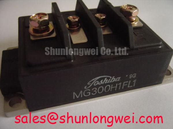
MG300H1FL1 IGBT Module: Technical Data for High-Reliability Power Systems
The Toshiba MG300H1FL1 is a 600V high-power switching module engineered for robust thermal management and operational longevity in demanding industrial power applications. Featuring a collector current rating of 300A and a low collector-emitter saturation voltage, this device provides a foundation for efficient and reliable power conversion. Its carefully specified thermal resistance is key to simplifying heatsink design and maintaining performance under heavy loads. What is the key benefit of its low thermal resistance? It allows for smaller heatsinks or higher power output in a given thermal envelope. For high-current industrial drives prioritizing thermal stability, this 300A module offers a robust and reliable core.
Key Parameter Overview
Decoding the Specs for Enhanced Thermal Reliability
The technical specifications of the MG300H1FL1 highlight its suitability for high-current, medium-voltage applications where thermal performance is a critical design constraint. The parameters below provide a snapshot of the module's capabilities, focusing on the electrical and thermal characteristics that directly influence system reliability and efficiency.
| Absolute Maximum Ratings (Tc = 25°C) | |
|---|---|
| Parameter | Value |
| Collector-Emitter Voltage (VCES) | 600 V |
| Gate-Emitter Voltage (VGES) | ±20 V |
| Collector Current (IC) | 300 A |
| Collector Power Dissipation (PC) | 1040 W |
| Operating Junction Temperature (Tj) | 150 °C |
| Electrical & Thermal Characteristics (Tj = 25°C unless otherwise noted) | |
|---|---|
| Parameter | Value |
| Collector-Emitter Saturation Voltage (VCE(sat)) | 2.7 V (Max) |
| Gate-Emitter Leakage Current (IGES) | 0.5 µA (Max) |
| Turn-On Time (ton) | 2.0 µs (Typ) |
| Turn-Off Time (toff) | 1.0 µs (Typ) |
| Thermal Resistance (Rth(j-c)) | 0.12 °C/W (Max) |
Application Scenarios & Value
System-Level Benefits in High-Current Power Conversion
The robust design of the MG300H1FL1 makes it a strong candidate for power conversion systems where reliability under demanding load cycles is paramount. Its primary value is realized in applications like industrial motor drives, high-power welding equipment, and uninterruptible power supplies (UPS).
Consider the engineering challenge within a high-frequency **Variable Frequency Drive (VFD)**. The constant, rapid switching of high currents generates significant heat within the power module. The MG300H1FL1's low junction-to-case thermal resistance (Rth(j-c)) of 0.12 °C/W is a critical parameter here. This specification acts like a wide pathway for thermal energy, allowing heat to escape efficiently from the active silicon to the heatsink. This prevents the junction temperature from exceeding its maximum limit, directly improving the VFD's long-term reliability and preventing premature failures. What this means for the design engineer is the potential for a more compact heatsink design or the ability to operate at higher ambient temperatures without derating, enhancing the overall power density of the final system. For systems requiring even greater current handling, the related CM400HA-24H offers a higher 400A rating in a similar class.
Technical Deep Dive
Analyzing the Construction for Superior Heat Dissipation
A closer look at the MG300H1FL1's architecture reveals a design focused on thermal efficiency. The module's construction utilizes a copper baseplate, which is essential for effective heat spreading from the IGBT and diode chips. This choice of material, combined with the manufacturing process, directly contributes to the low thermal resistance value specified in the datasheet. This Rth(j-c) value is not just a number; it represents the module's capacity to transfer internal heat to an external cooling system.
To put this in perspective, think of thermal resistance as the narrowness of a pipe. A high thermal resistance is like a very narrow pipe, causing a significant "pressure" (temperature) buildup at the source even with a small "flow" (power loss). The MG300H1FL1's low thermal resistance is akin to a wide, unobstructed pipe, allowing a large volume of heat to flow away from the junction with minimal temperature rise. This inherent efficiency in heat transfer is fundamental to the module's ability to operate reliably at its full 300A current rating and is a cornerstone for designing durable, high-performance power electronics like **Servo Drives** and power stages for industrial automation.
Frequently Asked Questions (FAQ)
How does the VCE(sat) of 2.7V impact the module's performance?
The collector-emitter saturation voltage (VCE(sat)) is the voltage drop across the IGBT when it is fully on. A lower VCE(sat) translates directly to lower conduction losses (Power Loss = VCE(sat) × IC). The 2.7V maximum rating at 300A signifies a balance between conduction and switching losses, contributing to overall system efficiency and reducing the amount of waste heat that needs to be managed by the cooling system.
What are the key considerations for a gate drive circuit designed for the MG300H1FL1?
A proper gate drive design is critical. Key considerations include providing the recommended gate-emitter voltage (typically +15V for turn-on, 0V or a negative voltage for turn-off) with sufficient peak current to charge and discharge the gate capacitance quickly. This ensures clean and efficient switching, minimizing switching losses. Additionally, incorporating short-circuit protection within the gate driver is crucial for protecting the module from catastrophic failure.
Can this module be used in applications with high switching frequencies?
The MG300H1FL1 is designed for high-power switching. Its typical turn-on (2.0 µs) and turn-off (1.0 µs) times are suited for applications operating in the low to mid-kilohertz frequency range, which is common for many industrial motor drives and power supplies. For very high-frequency designs, a detailed analysis of switching losses, as outlined in our guide to IGBT selection for high-frequency applications, would be necessary to ensure the thermal design can handle the increased power dissipation.
Engineering and Design Considerations
To fully leverage the capabilities of the MG300H1FL1, engineers should focus on optimizing the thermal interface. The selection of a high-quality Thermal Interface Material (TIM) and ensuring proper mounting torque are critical steps to minimize the contact thermal resistance between the module's baseplate and the heatsink. This meticulous approach to thermal management is essential for extracting maximum performance and ensuring the operational reliability of the end system. For design teams evaluating this component, detailed application notes and thermal modeling data can provide the necessary insights for a robust and efficient power stage design.