

Content last revised on November 4, 2026
Preventing Spurious Faults: Thermal Stress Alleviation in Bidirectional Guidelines for QM300HA-24
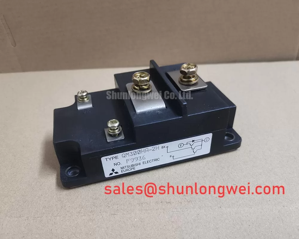
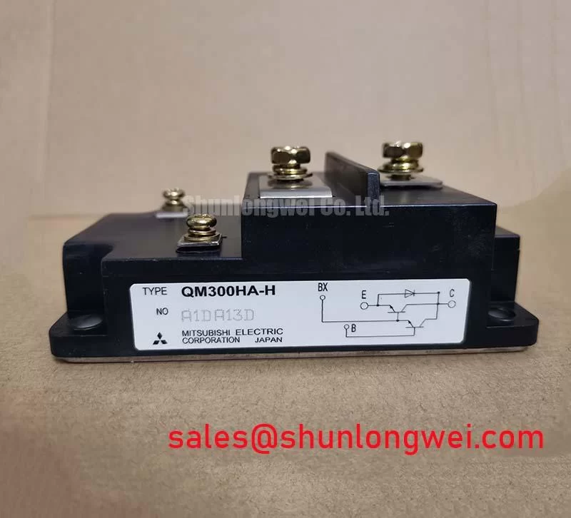
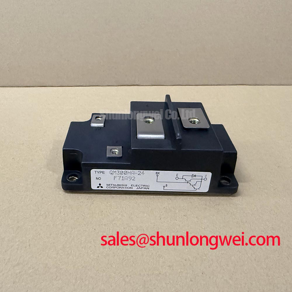
With the module isolated from its circuit, verify the terminal markings against the equipment drawing before using a meter’s diode mode; record the cold readings and compare them with a known-good unit of the same type. The specified identity for the Mitsubishi Electric QM300HA-24 is a 1200 V, 300 A Isolated Darlington Module. Those are the supplied ratings, not a complete switching or installation specification. Do not infer pin functions, gate limits, isolation-test conditions, or transient capability from the model name.
For battery-to-inverter and inverter-to-battery power flow, review the actual converter topology first: the QM300HA-24’s stated voltage and current ratings alone do not establish suitability for a bidirectional switching position. In a commercial string inverter or micro-grid storage system, trace each operating mode through the schematic and identify which device conducts or switches during charging, discharge, and regenerative events. Confirm that the module’s documented electrical characteristics match the circuit’s operating conditions before commissioning.
Peak shaving can create repeated changes in semiconductor loss as load and power direction vary. As a Design Consideration, assess thermal behavior across the intended operating cycle, not just at a single steady-state load. Check heatsink airflow, adjacent component spacing, enclosure temperature, and the mounting surface for obstructions or uneven contact. During troubleshooting, correlate protection events with load transitions and measured temperatures; a fault coinciding with a power reversal warrants checking the control sequence, current path, and thermal conditions rather than attributing it to one cause.
For repair planning, QM150DX-H is a related part to evaluate, not an assumed drop-in replacement. Compare its official ratings, terminal arrangement, switching characteristics, and mechanical interface with the installed device and system documentation. In the larger power path, CM2500DY-24S may be relevant as a separate topology component; its presence does not establish electrical compatibility with this module.
Field Diagnostics & Commissioning: Baseplate Isolation Breakdown Testing in QM300HA-24 Topologies
Before an insulation test, disconnect the module from the control board and power circuit, and follow the equipment maker’s isolation procedure. The supplied product data identifies an isolated module package but does not specify an insulation-resistance threshold, test voltage, or pass criterion. Do not apply the proposed 2.5 kV DC test or treat 500 MΩ as a QM300HA-24 acceptance limit unless the applicable manufacturer documentation explicitly permits that test method and voltage.
Inspect the mounting surface and surrounding area for conductive dust, residue, moisture, or damage that could create an unintended leakage path. If insulation testing is authorized for the assembled system, document the instrument, test configuration, and results, and compare them with the equipment’s stated requirements. A semiconductor module should not be exposed to an insulation tester while connected circuitry remains in the test path.
Check the protective fuse against the circuit’s documented fault-current coordination and the module’s applicable surge and safe-operating specifications. Fuse clearing performance cannot be established from the 1200 V and 300 A ratings alone. The table separates the known QM300HA-24 ratings from information requiring a datasheet comparison.
| Part | Category | Voltage rating | Current rating | Package |
|---|---|---|---|---|
| QM300HA-24 | Power transistor / Darlington module | 1200 V | 300 A | Isolated Darlington Module |
| QM150DX-H | Related module for evaluation | Consult datasheet | Consult datasheet | Consult datasheet |
Transient Dynamics & Electrical Design: Separating Driver Return from Main Current on QM300HA-24
Use the manufacturer’s terminal diagram to identify the power and control connections; do not assume this module provides a separate Kelvin emitter terminal. The supplied parameters do not include a pinout. During inspection, match every conductor to the module marking and equipment schematic, then check for loose connections, damaged insulation, or routing changes made during earlier repairs.
As an Engineering Recommendation, keep gate-drive wiring distinct from high-current paths where the documented terminal layout allows it. Switching current through shared impedance can shift the driver’s reference and disturb gate control. Keep the power loop compact and review the physical routing against the schematic; during commissioning, observe gate-to-emitter and switching-node behavior with suitable isolated measurement equipment. Any suppression, gate bias, or snubber values must come from the device documentation and system validation, not from the current and voltage ratings alone.
Module packaging and circuit topology affect how power devices connect to the rest of a converter; the power module architecture reference provides general context, not QM300HA-24-specific terminal data. Where phase-current feedback uses an isolated ADC, review the selected sensor’s interface and timing separately; delta-sigma modulation describes a conversion approach, not a feature confirmed for this module.
💡 Bench Tip: Use ESD precautions and compare cold measurements only with a known-good unit tested using the same meter, polarity, and setup.
Transient Dynamics & Electrical Design: Baseplate Thermal Grease Layer Control on QM300HA-24
Thermal-interface preparation depends on the module’s mounting instructions and the heatsink’s specified flatness and finish. The supplied QM300HA-24 data does not establish a thermal-grease thickness, baseplate curvature limit, or screw torque, so treat proposed values such as a 50–100 μm film as unverified rather than product specifications. Clean mating surfaces using a method compatible with the module and heatsink, and avoid trapped debris that could prevent uniform contact.
When mounting, follow the manufacturer’s tightening sequence and torque specification if available. Tighten progressively and evenly to reduce the risk of tilting the baseplate or loading one corner before the others. After assembly, inspect for displaced interface material and confirm that the heatsink contact area is unobstructed. For equipment-level reliability planning, the Industrial Applications guide offers broader application context; thermal limits and service life still depend on the device specifications and the assembled system.