
Content last revised on September 16, 2026
QM150DX-H Thermal-Electrical Optimization: Thermal Feedback Practical Tuning
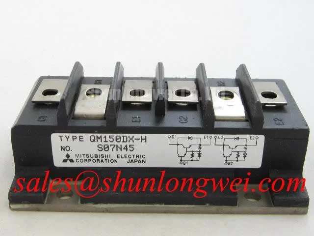
Before energizing a replacement assembly, verify the nameplate boundary and measure each accessible power path at room temperature with the drive isolated from its DC link. The QM150DX-H is a Mitsubishi Electric power transistor module with a 600 V collector-emitter voltage rating and a 150 A rated collector current, with PC 800 W, VISO 2500 V, and a specified junction-temperature range of −40 to +150 °C. These are Official Specifications and define the device boundary, not the allowable operating point of a completed motor drive.
For parallel current paths, the positive temperature coefficient of saturated collector-emitter voltage can support steady-state current sharing after thermal equilibrium. Dynamic sharing remains a separate concern. Design Consideration: route corresponding gate-drive paths with matched physical geometry, keep their return paths closely coupled, and confirm switching timing on the assembled power stage. Unequal loop impedance can create transient imbalance even where static measurements appear acceptable.
Thermal evaluation should begin with a clean, flat heatsink interface and a controlled mounting process, then compare case temperatures and switching waveforms under representative load transitions. A growing temperature difference may involve interface condition, airflow, gate timing, or a changed load profile; it should not be assigned to one cause without measurement. Field Alert: Disconnect and verify discharge of the DC link before removing gate or power connections from the module.
Where a repair evaluation requires a different current class, QM200HA-HK can be reviewed as a separate engineering candidate, with terminal arrangement, drive requirements, thermal interface, and protection thresholds checked against the original equipment documentation rather than assumed interchangeable.
Preventing Spurious Faults: Long Motor Lead Reflected Wave Voltage Guidelines for QM150DX-H
Start long-lead troubleshooting by probing at both the inverter output and the motor terminals with measurement equipment suited to the expected common-mode voltage. A motor cable behaves as a transmission path during fast switching, so impedance discontinuities can reflect voltage and produce terminal excursions approaching twice the DC-link voltage in some conditions. That mechanism is a Design Consideration, not an additional voltage rating for the 600 V module.
When traces show overshoot, ringing, nuisance protection events, or excessive radiated noise, evaluate cable length, shielding termination, output filter configuration, choke placement, and motor insulation suitability as one system. Designers should select and validate a dv/dt filter or output choke for the actual cable and motor combination, then verify peak collector-emitter stress against the DC-link voltage during switching tests.
The behavior of the freewheeling path also affects the waveform. Diode reverse-recovery behavior can interact with power-loop inductance and the commanded switching edge, changing ringing and EMI. Snubber networks can be assessed as a system-level mitigation, but their component values, loss, and thermal capability must be established from measured waveforms. Mitsubishi Electric publishes broader diode-module information at Mitsubishi Electric Diode Modules Lineup.
In a complete drive power chain, a module such as QM100HY-2H may be evaluated in its own specified role upstream or alongside the inverter stage. Its suitability depends on the implemented rectification, DC-link, protection, and mechanical arrangement.
QM150DX-H Operational Boundaries: Evaluating Sizing Braking Resistors and Chopper Trans Limits
During deceleration, inspect the DC-link trend before changing a braking resistor or chopper arrangement. Mechanical energy returned by the motor raises DC-link energy unless it is accepted by a regenerative path or dissipated through a braking circuit. The QM150DX-H ratings identify the module's stated electrical and thermal limits; they do not establish the braking-resistor energy rating, braking duty cycle, or chopper transistor capability.
Engineering Recommendation: determine the resistor and chopper requirements from the motor inertia, commanded deceleration, repeated-cycle duty, DC-link protection strategy, and enclosure heat removal. Verify the actual braking waveform and resistor temperature under the equipment's credible operating cycle. A DC-link trip can be related to insufficient energy absorption, control timing, input conditions, or measurement setup, so capture the relevant voltages and control commands before replacing parts.
Maintain appropriate creepage and clearance for the assembled voltage system according to the equipment insulation design and applicable standards. The module's 2500 V isolation voltage is an Official Specification, but it does not replace system-level evaluation of terminals, busbars, heatsink relationships, contamination, altitude, or enclosure conditions. For topology context when reviewing appliance-related resonant power stages, see Resonant Topologies in Home Appliances.
Benchtop Waveform Tuning: Mitigating Stress via Negative Gate Bias vs Active Miller Clamp on QM150DX-H
With the inverter disabled and the DC link controlled, examine the gate-emitter waveform during the opposite switch transition. High collector-voltage slew rate can couple through the Miller capacitance and raise the gate potential of a device intended to remain off. This may contribute to cross-conduction risk, but the waveform, driver reference, layout, and probe connection must be checked before drawing that conclusion.
Negative gate bias and active Miller clamping are alternative driver-level methods used to improve turn-off immunity. Their implementation is a Design Consideration: the system integrator should use only driver voltages and timing supported by the selected gate-driver documentation, minimize parasitic gate-loop inductance, and validate operation across the expected temperature and load range. Gate-drive isolation should also be assessed for common-mode transient behavior in the completed drive.
Use double-pulse or equivalent controlled switching tests to compare gate bounce, collector overshoot, current transition, and protection response after each layout or driver change. Pro Tip: Keep the DC-link bus arrangement physically symmetric around the commutation path, then verify turn-off peak margin with measured waveforms rather than layout intent alone. For background on Mitsubishi Electric power-device technology, refer to Mitsubishi Electric CSTBT™ Technology.