

Content last revised on September 19, 2026
J2-002A-F Product Identification and Available Specifications
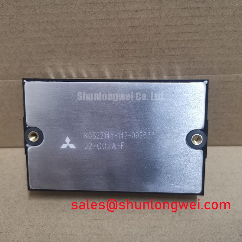
Before applying power, inspect the Fuji Electric J2-002A-F for package damage, confirm the terminal markings against the equipment drawing, and record a cold-state reference with the meter disconnected from every external circuit. The available product data identifies this device as a Power Transistor Module with a 2.0 A rated current and a Standard Industrial Rating for operating voltage. The available specification does not state an exact voltage value, internal circuit topology, terminal arrangement, thermal resistance, or insulation test rating; those points require confirmation from the original Fuji Electric documentation before replacement approval.
| Parameter | Available specification | Engineering use |
|---|---|---|
| Manufacturer | Fuji Electric | Verify the original equipment bill of materials and terminal drawing |
| Model | J2-002A-F | Use the complete suffix when checking mechanical and electrical interchangeability |
| Category | Power Transistor Module | Suitable for evaluation in industrial power conversion assemblies subject to circuit verification |
| Rated current | 2.0 A | Compare with the actual load, switching duty, cooling method, and overload profile |
| Operating voltage | Standard Industrial Rating | Confirm the exact voltage rating from the source documentation before energizing the circuit |
J2-002A-F Operational Boundaries: Evaluating Dynamic Control-Terminal Impedance for Robust Limits
For a heavy-duty variable frequency AC motor drive, the first integration task is to establish whether the J2-002A-F is connected as a switching transistor, a Darlington arrangement, or another power-stage configuration shown in the original schematic. The product category supplied for this part is a Power Transistor Module, but the available data does not confirm individual die connections or control-terminal names. Do not infer polarity from a visually similar module. Trace each terminal to the driver, DC link, emitter or return path, and protection network before applying a test signal.
Design Consideration: high dv/dt can couple through device capacitances and disturb a neighbouring control node. A control-terminal network with controlled impedance, a short return path, and an active Miller clamp where applicable can reduce the possibility of unintended turn-on, but the required clamp threshold, bias polarity, and control voltage must be taken from the original drive design and the applicable Fuji Electric data. The requested negative-bias range is not an official parameter available in the supplied information, so it should not be treated as a prescribed setting for this model.
During troubleshooting, compare the suspected channel with a known-good channel using an isolated differential probe. Check the command waveform, the device control-to-return waveform, and the switching-node response under the same test conditions. A simultaneous rise on a supposedly inactive control terminal may indicate capacitive coupling, an unsuitable return path, driver saturation, or measurement-loop error. It does not by itself prove module failure. Keep the high-voltage clearance and creepage arrangement consistent with the system insulation design and verify the actual peak voltage during switching tests.
For related topology review, engineers may compare the circuit role of QM100HY-2H when examining an associated rectifier or upstream power stage. This is a neutral reference point, not a compatibility recommendation. Any substitution requires confirmation of voltage, current, terminal geometry, drive requirements, and thermal behaviour.
Benchtop Waveform Tuning: Mitigating Stress via PCB Symmetry Considerations for J2-002A-F
The available specification does not confirm that J2-002A-F contains a dual IGBT circuit. If the equipment schematic shows two coordinated switching paths, treat the power return and control return as separate measurement problems. The main high-current emitter or return conductor should not share a long, inductive route with the auxiliary control reference. Mutual coupling can alter the apparent control voltage and produce ringing that is absent when the module is tested outside the assembly.
As a Design Consideration, route the power loop with the smallest practical area and place the driver return near the associated control terminal. Keep the auxiliary reference away from the high-current commutation path, and check the board for parallel copper runs that can transfer switching fields into the control circuit. The busbar arrangement should also be reviewed for stray inductance because turn-off overshoot is influenced by the interaction of current slope, loop inductance, damping, and device capacitance. The system engineer must verify peak margins against the DC-link voltage during controlled switching tests.
Thermal interface material should be applied as a uniform, continuous layer suited to the approved mounting surface; the correct thickness and material are system-dependent and are not specified in the supplied J2-002A-F data. Check the baseplate, heatsink flatness, contact pattern, and fastener sequence rather than assuming that a visually even compound layer provides even pressure. A cross-pattern tightening sequence is a general assembly practice, while the final torque must come from the module and heatsink mechanical documentation.
💡 Bench Tip: use ESD protection, discharge the DC link completely, and compare cold-state terminal measurements with the original module before connecting an oscilloscope or driver.
Preventing Spurious Faults: Thermal Time Constants and Peak Junction Guidelines for J2-002A-F
The specified 2.0 A rated current is only one part of the thermal decision. Pulse duration, switching frequency, case temperature, mounting pressure, cooling airflow, and overload repetition determine whether the junction can remain within its permitted operating area. No junction temperature limit, transient thermal impedance curve, or power-cycle rating is included in the supplied product data, so a numerical peak-junction calculation would be unjustified without the manufacturer’s curves.
For engineering evaluation, construct the thermal model from the official junction-to-case and case-to-heatsink data when available. A multi-RC network can represent short pulses more realistically than a single steady-state resistance, but the model must be fitted to authoritative thermal curves and then checked with measured case temperature and electrical loss. The calculated junction estimate should be compared with the manufacturer’s permitted operating limits under the actual pulse sequence, not with a generic semiconductor value.
When a drive reports an intermittent thermal or overcurrent fault, record the command waveform, collector or switching-node waveform where safely possible, case temperature, cooling condition, and fault timing. A fault that appears only during acceleration may involve current demand, commutation, gate timing, bus disturbance, or thermal accumulation. A fault that appears after repeated pulses may require review of the transient thermal response and mounting interface. These observations narrow the investigation without assigning a single cause prematurely.
Thermal-fatigue mechanisms are discussed generally in Power Cycling and Thermal Fatigue in Semiconductors. That reference should supplement, not replace, the device manufacturer’s qualification data. For broader system context, the Industrial Applications resource can help engineers relate power-module selection to larger industrial converter architectures.
Transient Dynamics & Electrical Design: Optimizing Heatsink Contact Pressure for J2-002A-F
The symbol S is sometimes used in engineering discussions for a soft-switching or reverse-recovery characteristic, but no diode recovery specification or S factor is provided for J2-002A-F. Do not assign a reverse-recovery value to this module from its product category alone. If a freewheel diode is present in the actual circuit, obtain its recovery curves and evaluate the resulting current commutation, electromagnetic interference, and DC-link overshoot using the complete power-stage schematic.
Common-mode and differential-mode noise require different current-path investigations. Review the distinction between these filter functions in Common-Mode Filter vs Differential-Mode Filter Design, then verify the actual noise path with a current probe or near-field measurement. A filter cannot correct an uncontrolled switching loop, poor return routing, or excessive mechanical contact resistance at the module base.
For heatsink installation, clean both contact surfaces, inspect for bowing or contamination, and apply only the interface material approved by the equipment manufacturer. Control the material spread through the assembly process rather than relying on a fixed universal thickness. Tighten the fasteners progressively in a cross pattern so the baseplate is not pulled unevenly toward one corner. The applicable screw size, torque, washer arrangement, and sequence remain installation-document requirements, not official electrical specifications for this part.
Before returning the drive to service, confirm terminal continuity against the approved schematic, verify isolation with the equipment’s authorized test method, and perform a staged low-energy switching test. Compare the control waveform, commutation overshoot, case temperature rise, and fault feedback with the original baseline. The QM200HA-HK may be reviewed as a separate product for cross-reference research, but its ratings and pin configuration must not be assumed interchangeable with J2-002A-F.