

Content last revised on October 21, 2026
FM600TU-2A Electrical Ratings and Fault Investigation
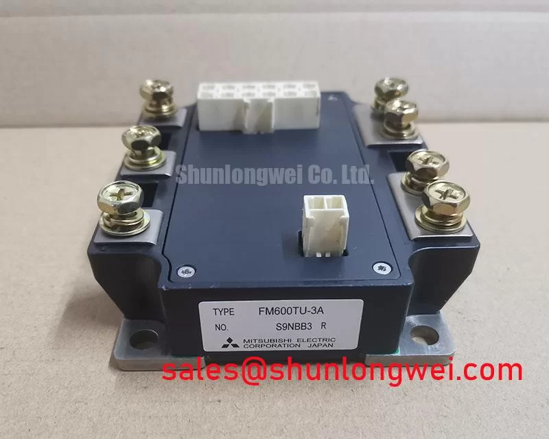
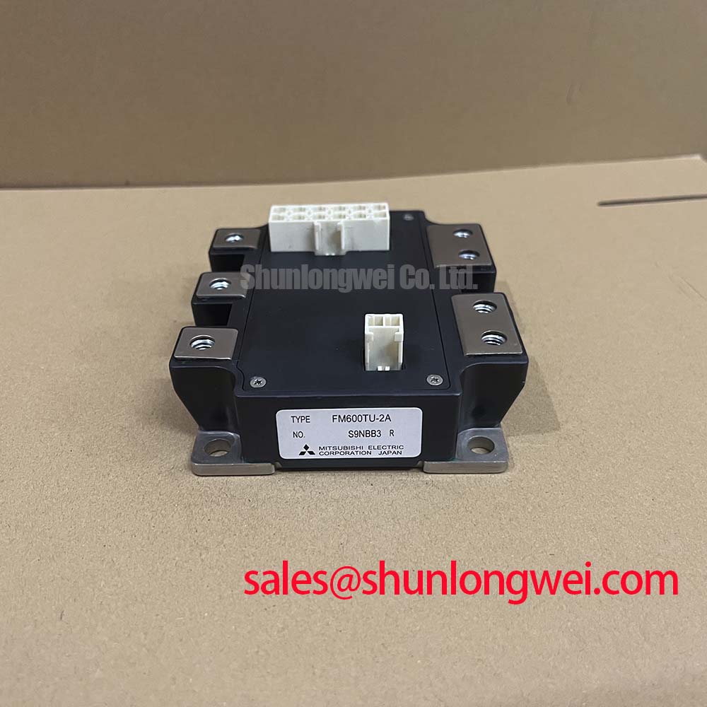
With the DC link discharged and verified safe, inspect the gate return wiring and power terminal connections before investigating intermittent trips around the FM600TU-2A. This Mitsubishi Electric power MOSFET module has specified electrical ratings of 100 V drain-source voltage, 300 A RMS drain current, and 600 A pulsed drain current. Its drain-source terminology matters when checking an existing schematic: gate protection and fault sensing must follow MOSFET behavior rather than assume IGBT characteristics.
The specified typical on-state resistance is 1.8 mΩ at 300 A drain current and 15 V gate-source voltage. Other specified limits include ±20 V gate-source voltage, 1040 W power dissipation per MOSFET, and a −40 to +150°C junction temperature range. These are device ratings, not simultaneous operating guarantees; the installed thermal path and switching conditions determine the usable operating envelope.
Preventing Spurious Faults: Galvanic Gate Drive Isolation and Reinforced Guidelines for FM600TU-2A
Trace the isolation boundary between the controller and gate driver, then examine whether switching transients disturb the driver output or its isolated supply. As a Design Consideration, select the driver’s insulation system and common-mode transient immunity against the actual working voltage, transient environment, and applicable equipment standard. Reinforced insulation is a system-level requirement, not a characteristic established by the module’s 2500 Vrms isolation voltage alone.
During controlled switching tests, observe gate-source voltage at the module terminals using appropriately rated differential measurement equipment. Compare a reported fault with the gate command, driver supply, and switching-node transition. A coincident disturbance can help distinguish a genuine gate excursion from a measurement artifact or a control-side interruption; it does not establish a single failure cause.
Keep the gate outgoing and return conductors close together, separate sensitive control routing from the power commutation path, and avoid shared return impedance between power current and the driver reference. These are Engineering Recommendations; clearance and creepage requirements should follow the equipment’s insulation coordination assessment rather than a generic spacing rule.
Mitsubishi Electric’s CSTBT™ and motion-control technology information provides broader power-device context, but CSTBT is IGBT technology and should not be attributed to this MOSFET module.
Transient Dynamics & Electrical Design: Preventing Terminal Overheating During Operation of FM600TU-2A
Measure bolted power-joint resistance with a four-wire micro-ohmmeter while the assembly is de-energized, placing the sense connections across the joint being assessed. Compare equivalent connections under consistent conditions rather than imposing an unsupported universal resistance threshold. During a controlled load test, thermographic comparison can reveal localized heating that warrants inspection of contact surfaces, fastening condition, or current distribution.
The integrated NTC thermistor supports temperature monitoring, but its reading is not automatically the instantaneous junction temperature or the temperature of a remote terminal joint. As a Design Consideration, interpret it alongside cooling conditions and the equipment’s thermal model. Likewise, the specified power dissipation requires its associated thermal conditions; it is not an allowance for arbitrary continuous losses.
Review protection using drain-source voltage and current behavior, not IGBT collector-emitter saturation terminology. MOSFET on-state voltage changes with current, gate drive, and temperature. Detection thresholds, blanking, propagation delay, and controlled turn-off should therefore be coordinated with validated fault behavior. A staged turn-off can reduce abrupt current interruption, but excessive delay can increase fault energy.
Semiconductor fuse coordination also requires more than matching nominal current. As an Engineering Recommendation, assess fuse clearing behavior and let-through energy against the complete fault path without assuming that a fuse guarantees survival of the MOSFET during a hard short circuit.
Practical design tip: Keep parallel power paths geometrically balanced to reduce unequal current sharing, and verify turn-off overshoot with a controlled double-pulse test. The discussion in Mastering Power System Dynamics provides supporting context for evaluating stray inductance and snubber behavior.
Preventing Spurious Faults: Negative Gate Bias vs Active Miller Clamping Guidelines for FM600TU-2A
Inspect the off-state gate waveform while the complementary switching position commutates, looking for Miller-induced excursions and oscillation. Reverse-transfer capacitance couples drain-voltage movement into the gate; it is not interchangeable with Miller plateau charge. Driver sink capability, gate-loop impedance, and common-source inductance all influence the resulting waveform.
As a Design Consideration, an active Miller clamp provides a local discharge path when its activation conditions are satisfied. Negative gate bias is another approach, but its suitability depends on driver behavior and measured excursions within the specified gate-source limit. Neither approach replaces adequate dead time: verify effective switching overlap across operating temperature and driver delay variation.
When evaluating compatibility with a compact industrial inverter or high-speed CNC spindle drive, check the actual DC-link envelope, circuit arrangement, cooling interface, and terminal geometry. The UM100CDY-10 can be included in a separate parameter comparison, not treated as an automatic replacement. Procurement records for the FM600TU-2A should retain the complete part designation and matched electrical and mechanical requirements.