Content last revised on September 10, 2026
Assembly Integrity & Layout Architecture: Implementing Dynamic Base-Drive Impedance Control for Robust Operation
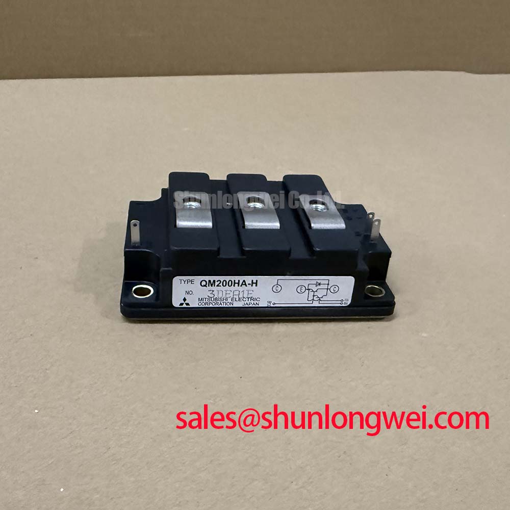
Before energizing a replacement assembly, verify the QM200HA-HK marking, inspect the power terminals and insulating surfaces, and measure cold-state impedance against a known-good unit using the approved service procedure. The listed Mitsubishi Electric specifications identify this power transistor and Darlington module with a 600 V VCES blocking rating, 200 A IC continuous collector current at the specified case condition, and 800 W PC total allowable power dissipation at 25°C.
Base-drive layout should keep the command loop physically separate from high-current commutation paths. A compact driver return, short base connection, and controlled base impedance help limit ringing and reduce the possibility of high dv/dt coupling into an inactive device. An active base-clamp or turn-off arrangement can be evaluated where the driver architecture supports it. Negative base bias is also a system-level option, but its polarity, magnitude, sequencing, and absolute base-emitter limits must be verified from the complete driver and module documentation rather than assumed from the module part number.
For a forklift traction inverter or electric material-handling drive, inspect the laminated busbar geometry, DC-link capacitor connection, and base-driver reference path together. Symmetrical current paths help reduce stray inductance and turn-off overshoot. During commissioning, use a differential high-voltage probe and confirm base-emitter voltage, collector-emitter voltage, and current timing under the actual battery and motor conditions. A fault that appears to be a base-drive failure may also involve ground-reference movement, connector contamination, or an incorrectly timed protection circuit.
💡 Pro Tip: Disconnect the DC-link source and follow the equipment discharge procedure before removing the driver or power terminals.
Transient Dynamics & Electrical Design: Evaluating Thermal Capacitance During Pulsed Operation
The QM200HA-HK is specified for a junction-temperature range of −40 to +150°C, with hFE = 75 minimum listed as the DC current gain under the specified test conditions. These values define component-level boundaries; they do not by themselves establish an allowable inverter duty cycle, overload duration, switching frequency, or heatsink size.
When a traction controller handles acceleration, regenerative braking, or bidirectional battery conversion, the thermal evaluation should account for both average dissipation and pulsed energy. A multi-RC thermal model can be used to estimate junction temperature from case temperature and the time profile of conduction and switching losses. The model should be correlated with thermocouple or resistance-temperature measurements at the mounting interface, then checked against the specified junction range.
Higher switching frequency generally increases switching loss, while repeated low-speed traction operation can raise conduction loss and reduce cooling effectiveness. Designers should therefore assess the complete operating map rather than select a thermal solution from the continuous current rating alone. Airflow, enclosure temperature, heatsink contact, thermal interface condition, and regeneration events all influence the result. For battery charging and discharging equipment, thermal cycling should be measured across the expected load sequence; no field-life or cycle-life value is established by the listed specifications.
Where a failed module is being replaced, compare the thermal interface condition, mounting flatness, cooling path, and base waveform with the original installation. The 800 W PC rating is an official listed specification at 25°C, but the practical dissipation limit remains dependent on the case temperature and system thermal resistance.
Assembly Integrity & Layout Architecture: Managing Common-Mode Motor-Bearing Current
Long motor leads can interact with cable capacitance, motor impedance, enclosure bonding, and inverter switching edges. The resulting common-mode current may stress bearings, cable insulation, connectors, and control references. Terminal voltage spikes should be confirmed with suitable measurement equipment rather than inferred from a visible waveform artifact or a single component failure.
For an electric forklift traction system, review motor-cable routing, shield termination, chassis bonding, and the physical relationship between the output conductors and sensitive signal wiring. Output filters or common-mode chokes may be appropriate, but their impedance, saturation behavior, voltage rating, and effect on control stability must be selected from measured system behavior. The inverter designer should verify peak terminal voltage against the DC-link boundary during switching tests and should examine the complete cable and motor combination.
Common-mode problems can also appear as encoder communication errors, unexplained driver resets, or intermittent protection trips. Compare the suspected phase-leg waveform with a known-good channel, inspect the base-driver supply reference, and check whether the disturbance follows the motor cable, switching leg, or control channel. The broader relationship between transistor switching, traction conversion, and industrial power systems is discussed in this Industrial Applications resource.
Topology decisions should remain application-specific. For systems using active rectification or related bidirectional current paths, engineers may consult the reference on Synchronous Rectification for Low Conduction Losses while verifying semiconductor voltage stress, commutation timing, and reverse-current behavior in the actual converter.
Benchtop Waveform Tuning: Checking Isolated Base-Drive Behavior
Optocoupler and digital coreless-transformer base drivers have different propagation, isolation, power-transfer, and common-mode transient characteristics. The correct choice for the QM200HA-HK application must be established from the driver datasheet, the module’s complete electrical documentation, and measured switching behavior. Do not treat a stated isolation class or transient-immunity target as a substitute for system-level verification.
On the bench, begin with a current-limited low-energy test and monitor both driver-side and power-side references. Check propagation delay matching, dead-time behavior, base-drive amplitude, Miller-induced movement on the inactive channel, and the response of saturation or overcurrent protection. Reinforced galvanic isolation, creepage, clearance, and common-mode transient performance should be reviewed against the required working voltage and installation environment. The Mitsubishi DIPIPM Bootstrap Circuit Design note provides useful background for evaluating bootstrap supply behavior, while the exact driver implementation remains system-dependent.
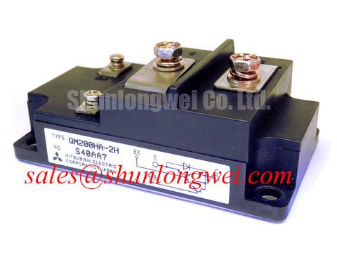
During field replacement planning, compare connector pin functions, driver polarity, protection timing, and mechanical interface before installation. The neutral compatibility reference for the QM100HY-2H may support a separate maintenance evaluation, but substitution requires confirmation of voltage, current, thermal, pin, and control compatibility in the original equipment documentation.