

Content last revised on October 15, 2026
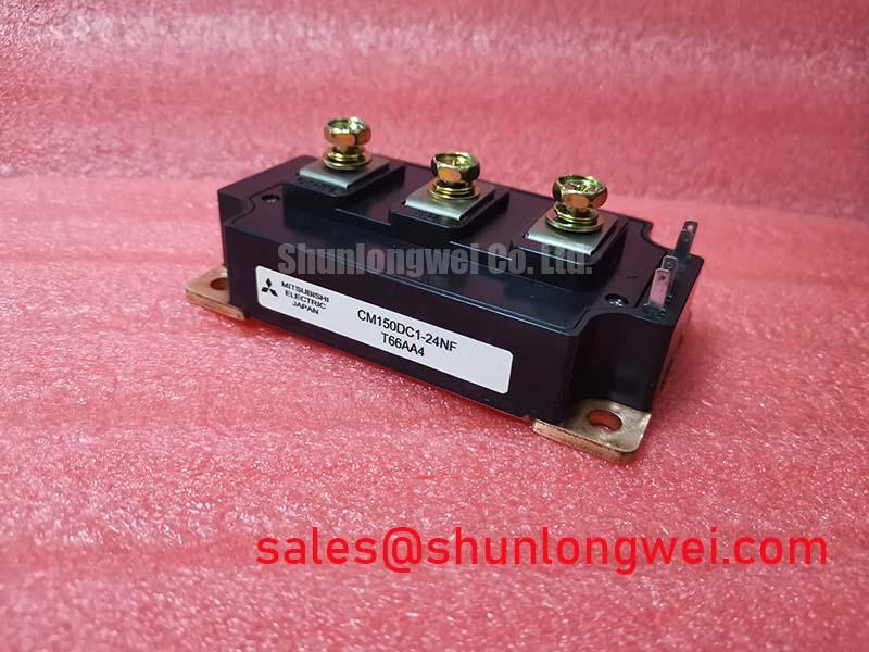
Transient Dynamics & Electrical Design: Thermal Stress Alleviation in Bidirectional Power Flow with CM150DC1-24NF
When a commercial string inverter or micro-grid storage converter shows excessive temperature cycling during charge and discharge transitions, I first isolate the DC power path, record the switching-node waveform under controlled conditions, and compare current rise and fall behavior between the battery-side and inverter-side operating states. The CM150DC1-24NF carries a datasheet voltage rating of 1200 V and a collector current rating of 150 A under the specified conditions in a module package; these ratings identify the device class, while the complete operating boundary remains dependent on the converter topology, cooling arrangement, switching conditions, and protection network.
Four-quadrant power flow places different thermal demands on the semiconductor during battery charging, regenerative operation, and peak-shaving discharge. A practical design consideration is to examine whether commutation paths remain electrically symmetrical in both current directions. Unequal busbar length, shared return inductance, or a physically remote freewheel path can increase switching overshoot in only one quadrant. Engineers should place voltage probes directly across the relevant power terminals, use a low-inductance measurement connection, and compare the observed peak with the device’s blocking-voltage rating, allowing an appropriate design margin during both energy-flow directions.
High-current connections also require attention to insulation geometry. Maintain the creepage and clearance required by the system insulation class, pollution environment, working voltage, and applicable safety standard rather than copying spacing from an unrelated module. The module’s 1200 V rating does not define the complete assembly insulation rating. Adjacent copper, busbar edges, fasteners, and contamination paths should be reviewed together, particularly around the DC link and gate-drive interface.
For protection coordination, the semiconductor fuse must be evaluated against the converter’s prospective fault current and the module’s permitted short-circuit behavior. The fuse’s let-through I²t, clearing time, wiring inductance, and current-limiting performance should be assessed as one protection system. A fuse selected only by continuous current can leave the module exposed during a high-energy fault. During service diagnosis, inspect fuse operation, gate-drive shutdown timing, and the condition of the DC-link discharge circuit before applying a replacement module.
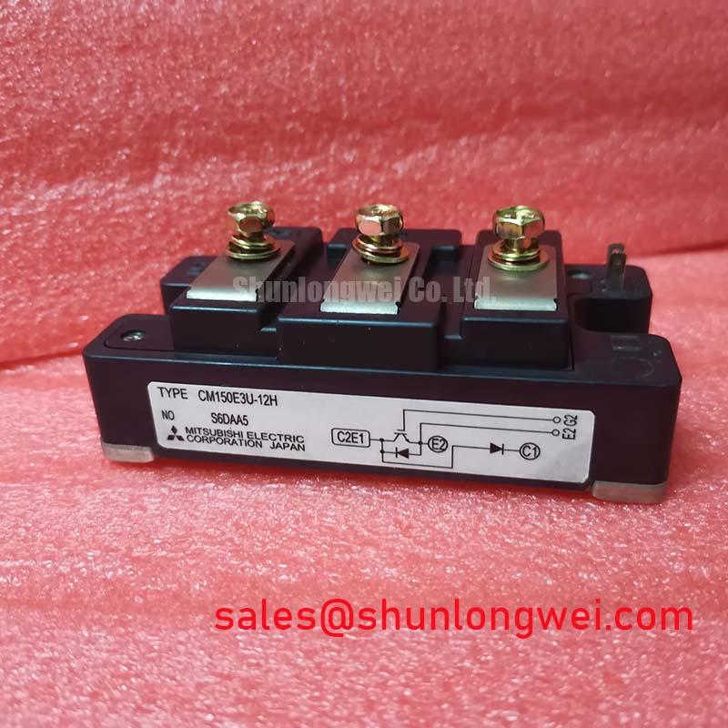
For topology comparisons, the CM150DY-12NFA can be reviewed as a related Mitsubishi Electric module, but pin arrangement, ratings, and mechanical compatibility must be checked independently before any substitution. The manufacturer’s power semiconductor reference material is available from Mitsubishi Electric Power Semiconductors & High-Power Modules.
Benchtop Waveform Tuning: Mitigating Stress via Symmetrical Busbar Geometry for High-Current Operation with CM150DC1-24NF
For a converter using parallel switching paths, symmetrical busbar geometry is the first practical check when current sharing appears uneven. Keep the positive and return conductors physically comparable, avoid forcing one module to carry a longer commutation loop, and route gate-drive conductors so that each switching position sees a similar electrical environment. The final arrangement is a system design decision that must be confirmed through current-probe and oscilloscope measurements.
In static sharing discussions, the positive temperature coefficient commonly associated with IGBT saturation voltage can help distribute current between suitably matched parallel devices. This is a design consideration, not an automatic guarantee for every parallel arrangement. Dynamic sharing is controlled by stray inductance, gate-loop impedance, driver propagation timing, emitter reference integrity, and thermal coupling. If one waveform reaches its plateau earlier or shows a larger turn-off excursion, inspect the complete gate and power loop rather than adjusting only the gate resistor.
Bench testing should begin at a controlled operating point and progress while observing collector-emitter voltage, gate-emitter voltage, and current simultaneously. Compare turn-on delay, Miller-region behavior, turn-off overshoot, and ringing between parallel positions. Any change to busbar geometry should be followed by another thermal and waveform check because a visually shorter connection is not necessarily electrically balanced.
The CM200DY-12NFH may be evaluated as a related device in an upstream rectification or complementary converter stage, subject to its own electrical, mechanical, and control-interface verification. It should not be treated as an automatic companion or replacement for the CM150DC1-24NF.
Benchtop Waveform Tuning: Mitigating Stress via Preventing Ceramic Substrate Rupture during Installation of CM150DC1-24NF
Mechanical flatness deserves attention before waveform tuning because uneven support can create local thermal resistance and mechanical stress beneath a power module. Place the module on a clean heatsink surface, inspect the baseplate and heatsink for visible convexity or contamination, and confirm that the mounting holes align without forcing the package sideways. The heatsink surface, fastener sequence, and thermal interface material must be treated as one assembly process.
Apply thermal interface material as a uniform, controlled layer suitable for the chosen compound and surface finish. The frequently used 50–80 μm range is a general industry assembly reference, not an official CM150DC1-24NF specification; the actual layer should be validated by the equipment builder. Tighten fasteners progressively in a diagonal cross-pattern so the pressure develops evenly across the module rather than concentrating at one corner.
⚠️ Field Alert: Follow the module manufacturer’s mounting torque specification and use a calibrated torque tool; excessive or uneven tightening can damage the substrate or distort the thermal contact.
After installation, check that the module remains seated without rocking, that terminals are not mechanically loaded by rigid busbars, and that the gate-drive connector or wiring does not pull against the package. Recheck electrical insulation, terminal tightness, and thermal behavior after the first controlled run. For broader converter layout guidance involving multi-level architectures and energy-storage power flow, review Peak Efficiency in Solar and Energy Storage.