

Content last revised on September 25, 2026
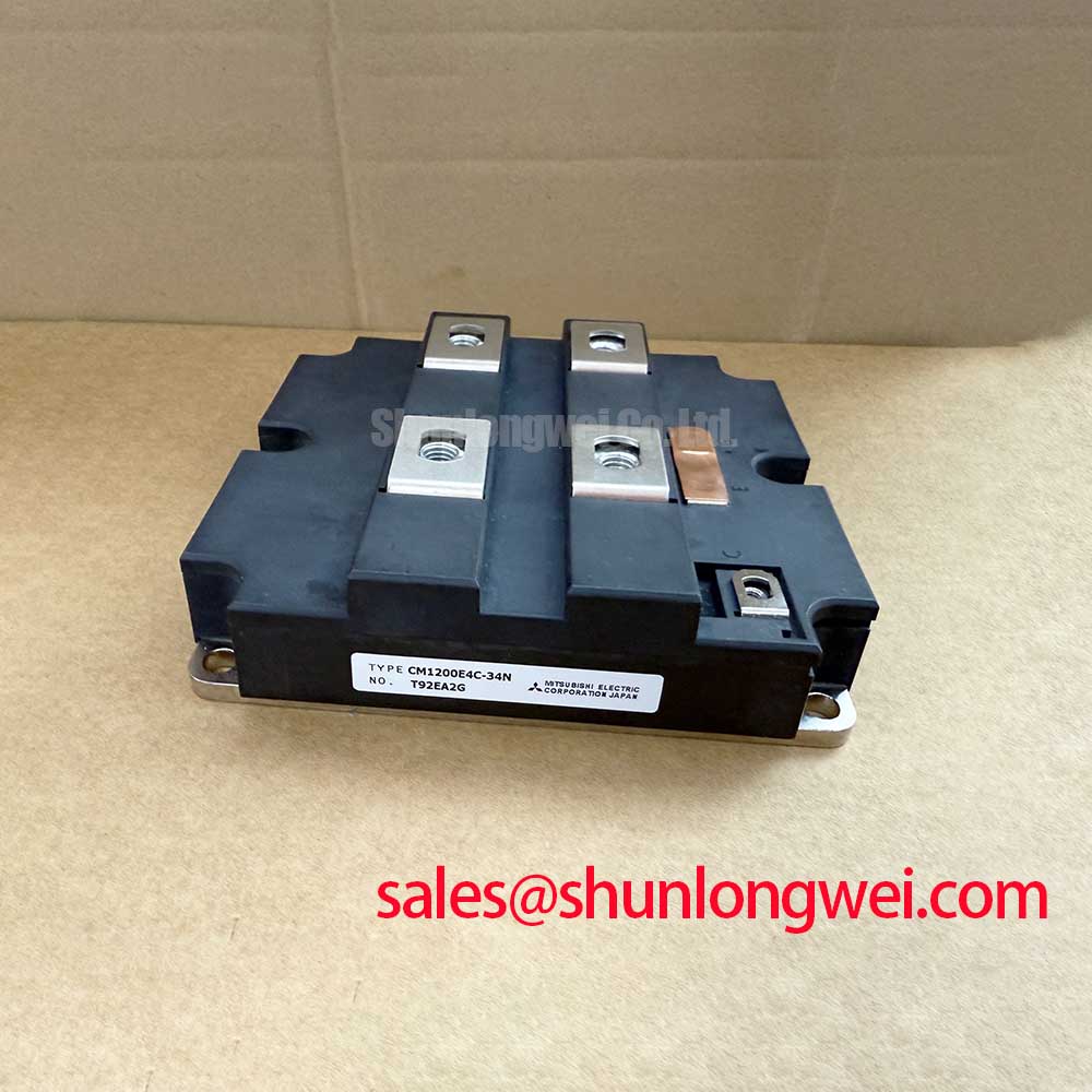
Transient Dynamics & Electrical Design: Reinforced Insulation Barrier Integrity and CM1200E4C-34N
At commissioning, check the gate driver isolation boundary and the physical separation between control wiring and high energy power conductors before energizing the 1700V CM1200E4C-34N. Reinforced galvanic isolation, common mode transient immunity, and isolation withstand capability are properties of the complete driver and converter implementation. They are not confirmed module ratings from the available product parameters, so values such as reinforced isolation above 5kV or CMTI above 100kV per microsecond must be verified from the actual gate driver and system documentation.
Design Consideration: fast collector voltage movement can couple through parasitic capacitance and shared return paths into low voltage control circuits. A gate command that appears distorted at the driver output may arise from return path impedance, control cable routing, insufficient isolation performance, or probe connection error. Compare the affected phase against a known stable phase using correctly rated differential measurement equipment, while observing the driver supply, gate emitter reference, desaturation or fault signal, and collector emitter waveform together.
Keep high current switching loops physically compact and route sensitive control conductors away from busbars, braking resistor leads, and motor output cables. The objective is to reduce parasitic coupling that can create unwanted gate disturbance during switching. System engineers should verify peak collector voltage, gate voltage stability, and protection timing under the actual DC bus condition, load current, and operating temperature rather than relying on static bench measurements alone.
The product family context can be reviewed through Mitsubishi Electric Power Semiconductors and High Power Modules, while the final integration boundary remains the responsibility of the equipment designer and maintenance authority.
Field Diagnostics & Commissioning: High Altitude Cosmic Ray Induced SEB Failure in CM1200E4C-34N Topologies
For equipment intended for operation at elevated altitude, begin with the original converter environmental specification and the semiconductor manufacturer’s application documentation. No authoritative FIT rate, single event burnout rate, altitude derating curve, or cosmic ray robustness data has been provided for the CM1200E4C-34N. It would therefore be inappropriate to calculate a failure in time value or claim a defined DC bus derating for this module.
Design Consideration: terrestrial neutron exposure and reduced cooling capability at altitude are system reliability topics that require qualified component data and a documented operating profile. When an installation is expected to operate above 2000m, engineers should evaluate insulation coordination, cooling performance, DC bus voltage limits, protection response, and any applicable manufacturer guidance as a connected design review. This applies equally to equipment being considered for high speed rail or heavy freight locomotive traction inverter service, subject to the vehicle converter’s original approval requirements.
During field diagnosis, do not attribute a failed switching position to a single environmental mechanism without evidence. Inspect stored fault records, phase current balance, brake chopper operation, cooling airflow, DC link condition, and gate driver fault history. A braking resistor circuit deserves particular attention during regenerative events because its switching device and energy absorption path are exposed to repetitive high energy duty determined by the wider converter system.
Freewheeling diode reverse recovery behavior can also influence turn off stress and conducted or radiated noise. A sharp recovery waveform may combine with busbar inductance and capacitor placement to produce overshoot or ringing. Engineering Recommendation: capture waveforms at the module terminals with suitable high voltage instrumentation, then assess whether the existing snubber network, laminated busbar arrangement, and DC link capacitor connection are functioning as intended. The CM300DXDX1-24A may be relevant for reviewing an associated rectifier or auxiliary power stage where the converter topology uses such a device.
Assembly Integrity & Layout Architecture: Implementing Transmission Line Impedance Mismatch Sizing for CM1200E4C-34N
Confirm that the mounting surface is clean, flat, and free of residue before placing the module on its heatsink. Apply the thermal interface material according to the original equipment procedure, then tighten the specified hardware in the prescribed sequence so that mounting pressure is distributed across the module baseplate. The correct bolt size, tightening torque, thermal material thickness, and any disc spring arrangement must be taken from the converter or module documentation because those values are not established by the supplied product data.
⚠️ Maintenance Note: Periodically monitor terminal contact temperature rise and confirm that cooling fins, fan paths, and clamping hardware remain clean and secure during scheduled maintenance.
Long motor cables should be treated as transmission paths rather than simple conductors. Under fast switching conditions, impedance discontinuities at the inverter output, cable, and motor terminals can reflect voltage waves, and terminal stress can approach twice the DC link voltage in some system conditions. This is a Design Consideration, not a guaranteed behavior of the CM1200E4C-34N. Cable length, motor impedance, switching waveform, output filter design, grounding architecture, and measurement location all influence the observed result.
When repetitive reflected wave concerns are identified, designers should assess the motor terminal waveform and determine whether an output reactor, dv per dt filter, sine filter, shielding arrangement, or cable routing change is appropriate for the actual drive system. The filter and choke values must be determined through system testing because a fixed prescription cannot account for motor type, cable construction, switching frequency, and converter control strategy.
At the module end, minimize the commutation loop between the DC link capacitors, power terminals, and switching path to suppress turn off inductive overshoot. Laminated busbars can help reduce loop area when correctly integrated, but their effectiveness must be verified through switching tests that compare peak voltage margins with the operating DC link voltage. Recheck terminal tightness after thermal cycling if the equipment service procedure requires it.
Preventing Spurious Faults: Dynamic Power Loss Dissipation and Multi RC Guidelines for CM1200E4C-34N
A converter can show intermittent overtemperature, desaturation, or overcurrent events even when static insulation and resistance checks appear acceptable. Start by checking heatsink cleanliness, fan direction, airflow obstruction, coolant condition where applicable, thermal interface aging, terminal contact condition, and the consistency of gate driver supply rails. These observations establish whether the fault is likely associated with thermal transfer, power path resistance, driver behavior, sensing, or control timing.
Dynamic power loss is determined by the converter’s switching current, voltage, switching frequency, gate drive behavior, freewheeling path, and load duty cycle. The module’s 1700V and 1200A ratings do not independently define junction temperature during a pulsed overload. A multi RC thermal model can be useful when the manufacturer provides the relevant transient thermal impedance data, because it represents how heat propagates from the silicon junction toward the case over time. Without that official thermal model and the actual switching loss data, a numerical junction temperature prediction should not be presented as a verified result.
Engineering Recommendation: correlate converter fault timestamps with measured case temperature, cooling status, phase current, DC link voltage, and switching waveform. If the event coincides with regenerative braking, verify the braking chopper command, resistor continuity, resistor cooling condition, and DC link response. If it appears during motor acceleration or long cable operation, inspect output current symmetry and switching ringing before changing protection thresholds.
Power semiconductor technology selection and system level switching tradeoffs can be explored through Wide Bandgap Revolution. For manufacturer technology context, consult Mitsubishi Electric Global Semiconductor Device Technologies alongside the original converter documentation.