


Content last revised on March 27, 2026
TDK-Lambda DPF1000 PFC Module: Advanced Power Factor Correction for High-Density Systems
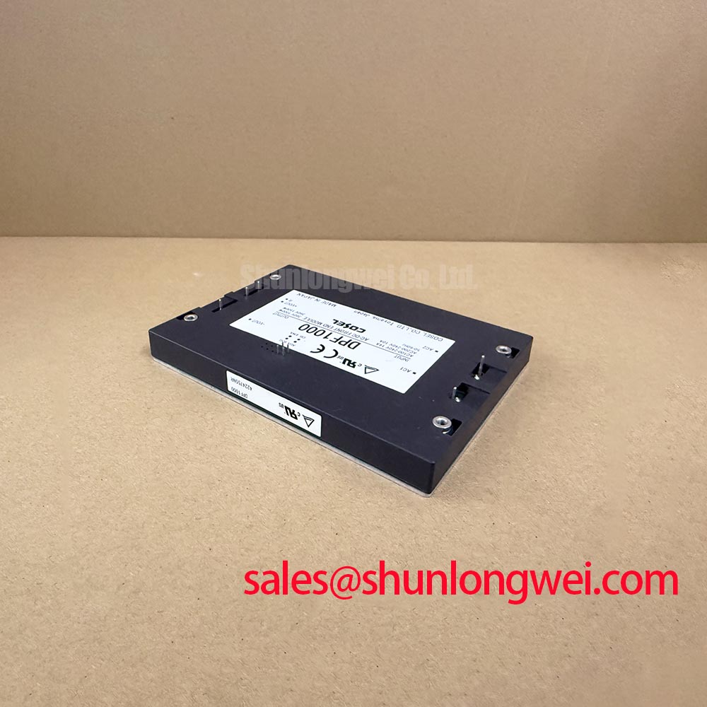
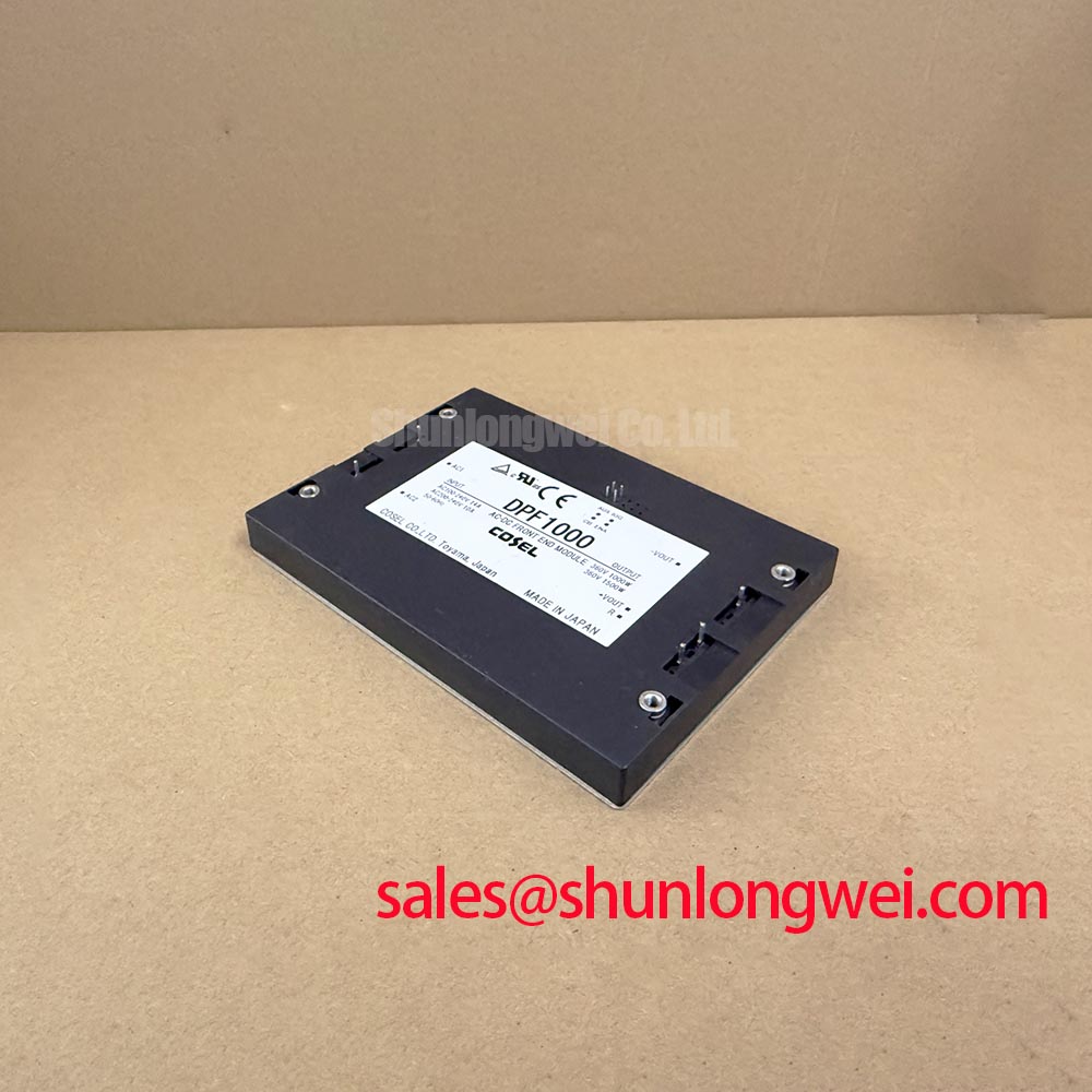
The DPF1000 is a high-performance, 1000W Power Factor Correction (PFC) module engineered to serve as the critical front-end for distributed power architectures. By providing a 360VDC output from a universal 85–265VAC input, this module enables engineers to meet stringent harmonic regulations while maximizing usable power. It achieves a power factor of 0.95 or higher, significantly reducing Switching Loss and reactive power strain on the grid. For industrial power front-ends requiring harmonic compliance and 1000W density, the DPF1000 is the most reliable conversion stage.
Application Scenarios & Value
Achieving System-Level Efficiency in Industrial Front-Ends
Engineers often face challenges with harmonic distortion and efficiency losses when designing high-power industrial equipment. The DPF1000 addresses these pain points by integrating a full-bridge rectifier and a boost converter into a single, high-density brick format. In a typical Variable Frequency Drive (VFD) or high-power Solar Inverter, the DPF1000 ensures that the input current remains sinusoidal and in phase with the voltage, which is essential for compliance with IEC 61000-3-2 standards.
In large-scale data center power supplies or medical imaging systems, the module acts as the pre-regulator for downstream IGBT modules. By providing a stable 360VDC bus, it protects sensitive components from line voltage fluctuations. For engineers designing monitoring interfaces for these systems, integrating a reliable industrial display like the G150XNE-L01 or the NL8060BC31-28E allows for real-time visualization of power quality metrics. While this module is optimized for 1000W loads, systems requiring distributed control often pair this with low-latency communication stages to ensure Thermal Management stability across the entire power train.
Technical Deep Dive
Optimization of Harmonic Suppression and Power Density
The DPF1000 utilizes an advanced high-frequency switching topology to achieve a peak efficiency of approximately 95%. This efficiency is critical because it minimizes the heat that must be dissipated within the cramped confines of a system enclosure. Think of the Power Factor as the "efficiency of a straw"; a low power factor is like trying to drink a milkshake through a straw full of holes—you exert a lot of effort (current) but get very little liquid (active power). The DPF1000 "plugs those holes," ensuring that almost 100% of the current drawn from the AC line is converted into useful DC work.
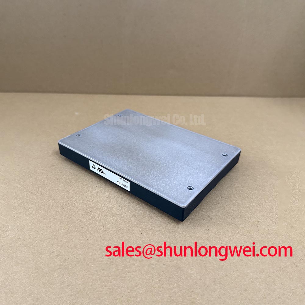
Technically, the module features an internal Inrush Current Limiting circuit, which prevents massive current spikes during startup that could otherwise trip circuit breakers or damage the IGBT Module stages. The baseplate-cooled design allows for Thermal Resistance management through direct mounting to a cold plate or heatsink. This mechanical robustness is essential for mission-critical applications where Switching Loss at high frequencies must be mitigated to prevent localized hotspots. By maintaining a stable output voltage even during "brownout" conditions (as low as 85VAC), the DPF1000 provides a layer of immunity against poor power grid quality.
Key Parameter Overview
Decoding Specs for Enhanced Power Integrity
| Key Parameter | Technical Value | Engineering Significance |
|---|---|---|
| Input Voltage Range | 85 – 265 VAC | Full universal AC input for global deployment without hardware changes. |
| Output Power | 1000 W | High power density in a standard brick footprint for space-constrained designs. |
| Output Voltage | 360 VDC | Optimized bus voltage for high-efficiency DC-DC converters and motor drives. |
| Power Factor | > 0.95 | Exceeds IEC61000-3-2 requirements for harmonic current emissions. |
| Efficiency | ~95% | Reduces thermal load on the Thermal Management system and lowers TCO. |
Download the DPF1000 datasheet for detailed specifications and performance curves.
FAQ
How does the Power Factor of 0.95 directly impact the selection of upstream cabling and fuses?
A power factor of 0.95 means the RMS current drawn is significantly lower than a non-PFC load of the same wattage. This allows engineers to use smaller gauge wiring and lower-rated circuit breakers, reducing the total cost of the electrical installation.
Can the DPF1000 operate at its full 1000W rating across the entire input voltage range?
Most PFC modules require derating at low-line (85-115VAC) due to the higher input currents. Engineers must consult the DPF1000 thermal derating curves to determine the maximum allowable baseplate temperature when operating at 100V line inputs.
What is the primary benefit of the module's baseplate-cooled mechanical structure?
The baseplate design allows for the conduction of heat away from internal semiconductors to an external heatsink. This is vital for maintaining high reliability, as it keeps the internal junction temperatures well below their limits even during continuous 1000W operation.
Does the DPF1000 include internal protection against AC line surges?
While the module handles standard fluctuations, it is recommended to use an external Snubber Circuit or MOV at the system entry point to protect against high-energy transients, ensuring the longevity of the module's internal rectifier bridge.
From a strategic perspective, the DPF1000 represents a shift toward modular, high-efficiency power design that aligns with global green energy initiatives. As industrial standards for Power Quality become increasingly strict, utilizing a proven PFC stage becomes a necessity rather than an option. By integrating this module, OEMs can future-proof their systems against evolving electromagnetic compatibility (EMC) regulations while benefiting from a simplified design-in process.