Content last revised on September 10, 2026
Preventing Spurious Faults: Evaluating Thermal Capacitance vs Heat Sink Guidelines for QM100HY-2H
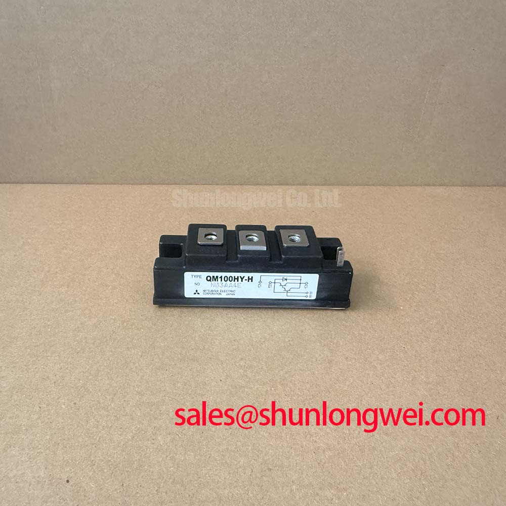
With the drive isolated and discharged, first compare the QM100HY-2H terminal identification against the original equipment schematic, then use a diode test function only as a cold comparison between like modules from the same assembly. The QM100HY-2H is a Mitsubishi Electric power transistor Darlington module with an official VCEX rating of 1000 V and IC DC rating of 100 A. Its published typical DC current gain is hFE 75 at 100 A and 2.8 V. These values establish the electrical identity that must be checked before a repair board is returned to service.
| Official specification | Value | Integration relevance |
|---|---|---|
| Collector emitter voltage, VCEX | 1000 V | Transient turn off voltage must remain below the stated operating boundary. |
| DC collector current, IC | 100 A | Conductor sizing and cooling capability must be validated at the actual duty cycle. |
| DC current gain, hFE | 75 typical at 100 A, 2.8 V | Base drive performance materially affects conduction behavior. |
| Emitter base voltage, VEBO | 7 V | Reverse emitter base stress requires controlled drive conditions. |
For a heavy duty variable frequency AC motor drive, begin fault isolation by separating a true power stage overtemperature event from a sensor, airflow, or control interlock issue. The supplied official information defines voltage, current, gain, and emitter base limits, but does not provide a published transient thermal impedance curve, thermal capacitance value, junction temperature limit, or surge current ITSM rating. A junction to case transient calculation using a multi RC thermal model therefore cannot be represented as an official QM100HY-2H result without the original thermal data.
As a Design Consideration, an engineer can use the drive manufacturer’s qualified thermal model to assess whether repetitive overload pulses allow sufficient junction temperature recovery before the next pulse. Measurements should include case temperature, cooling path condition, load current waveform, and the duration of regenerative braking events. A braking chopper and its power resistor can alter the DC link energy balance during deceleration, so their operation should be checked as part of the system rather than assigning a single thermal cause to the transistor module.
The stated 1000 V VCEX rating is an Official Specification. The supplied design constraint calls for a snubber clamp that keeps turn off spikes below 900 V. This is a circuit requirement associated with the provided integration context, not a replacement for measuring the installed waveform. Minimize the commutation loop area to suppress inductive overshoot, then verify collector emitter peak voltage against the DC link and the module rating using properly referenced switching measurements.
Where replacement evaluation is necessary, engineers should compare the circuit topology, terminal arrangement, drive method, thermal interface, and all electrical limits rather than relying on a shared current figure. The QM100DX-H can be reviewed as a separate module option, but compatibility remains dependent on the original equipment schematic and verified operating conditions.
Assembly Integrity & Layout Architecture: Implementing Baseplate Thermal Grease Layer Control for QM100HY-2H
Before fastening the QM100HY-2H, inspect the heatsink contact area for raised burrs, trapped debris, corrosion, or uneven residue from the removed module. These conditions can create localized contact resistance that affects case temperature interpretation. Apply thermal interface material as a continuous controlled layer rather than a thick reservoir. A 50 to 100 μm grease layer is a general industry Design Consideration for flat power module interfaces; the final process must follow the heatsink flatness, grease supplier, and equipment manufacturer requirements.
Bring the module down evenly using a diagonal tightening sequence so that the baseplate settles progressively against the heatsink. A staged sequence helps avoid trapping air and accommodates minor assembly variation without assuming an unverified baseplate curvature value. Fastener torque must be taken from the module documentation or original drive service procedure because the supplied official data does not identify screw size or torque.
💡 Bench Tip: Keep ESD controls in place and record cold diode test observations before removing the original module, because a same board comparison is more useful than applying an assumed universal reading.
At switching frequencies from 2 kHz to 16 kHz, the system thermal result is determined by load waveform, commutation behavior, base drive, heatsink performance, ambient temperature, and airflow. This frequency range is an evaluation condition, not an official QM100HY-2H switching frequency rating. When integrating the module, designers should test case temperature and electrical waveforms at the actual frequency and load profile, especially where a motor drive experiences repeated acceleration, deceleration, or braking resistor duty.
Base Drive and Thermal Feedback for QM100HY-2H
The published typical hFE of 75 at 100 A and 2.8 V should be treated as an Official Specification at the stated test condition, not as a fixed gain across temperature, current, or dynamic switching. The provided circuit constraint specifies a stable 5 A base drive to reduce saturation loss. This base drive requirement should be checked against the original driver board, connector path, base return routing, and the equipment manufacturer’s drive timing documentation.
Thermal feedback for this module should be based on measured system conditions. A case mounted or heatsink mounted sensor may help reveal cooling changes, but it does not directly establish junction temperature without a validated thermal relationship. If parallel power paths are present in the equipment, the positive temperature behavior of saturation voltage can support steady state current sharing under controlled conditions. Dynamic current balance still depends heavily on symmetrical base loop wiring, common return impedance, and switching timing.
As an Engineering Recommendation, compare the voltage drop and current waveform of each parallel path under the same load condition, then inspect for unequal conductor length, loose bus connections, degraded drive output, or nonuniform heatsink contact. A waveform imbalance may indicate several interacting causes and should be verified with an oscilloscope against a known good path. For structured test sequences and fault evidence collection, refer to the Field Engineer’s Handbook.
Benchtop Waveform Tuning: Mitigating Stress via Active Miller Clamp Implementation on QM100HY-2H
Active Miller clamp circuits and negative gate bias are concepts associated with voltage controlled IGBT or MOSFET gate drive systems. The QM100HY-2H is identified here as a Darlington power transistor module with a base drive requirement, so an active Miller clamp cannot be presented as a direct QM100HY-2H implementation instruction. Likewise, applying an assumed negative gate bias would be inappropriate terminology and could create harmful emitter base reverse stress.
The official VEBO rating is 7 V, while the supplied circuit constraint requires reverse bias to be clamped below 5 V to protect junction integrity. This should be treated as a strict drive path verification item. Inspect the base emitter return route, driver output state during power sequencing, parasitic coupling from collector switching, and any suppression network specified by the original drive design. The goal is to prevent unintended base emitter stress while preserving the intended turn off behavior.
A low impedance controlled base discharge path is a Design Consideration when collector voltage slew can couple disturbance into a transistor drive loop. The appropriate component values, polarity, and timing are system determined and must be confirmed through switching tests that verify collector emitter overshoot, base emitter voltage, current fall behavior, and DC link conditions. For background on bootstrap supply behavior in power device driver systems, Mitsubishi Electric’s DIPIPM™ Bootstrap Circuit Design note provides relevant driver supply principles, although its device specific implementation must not be transferred directly to this Darlington module.