


Content last revised on October 13, 2026
100L6P41 Inspection and Replacement Considerations
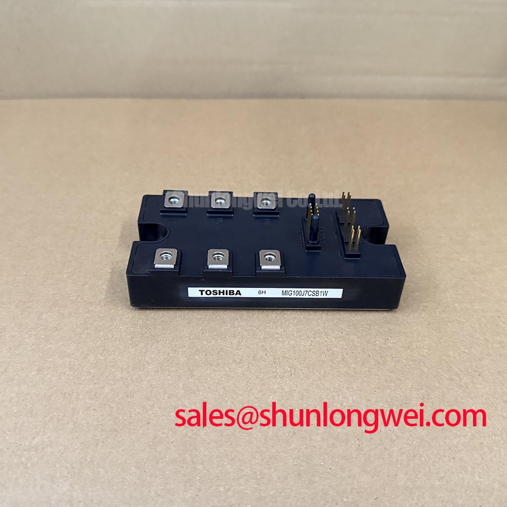
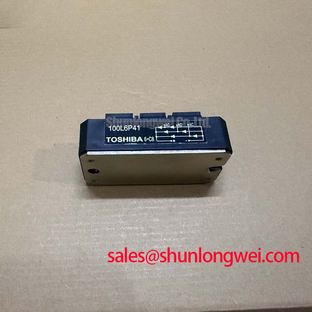
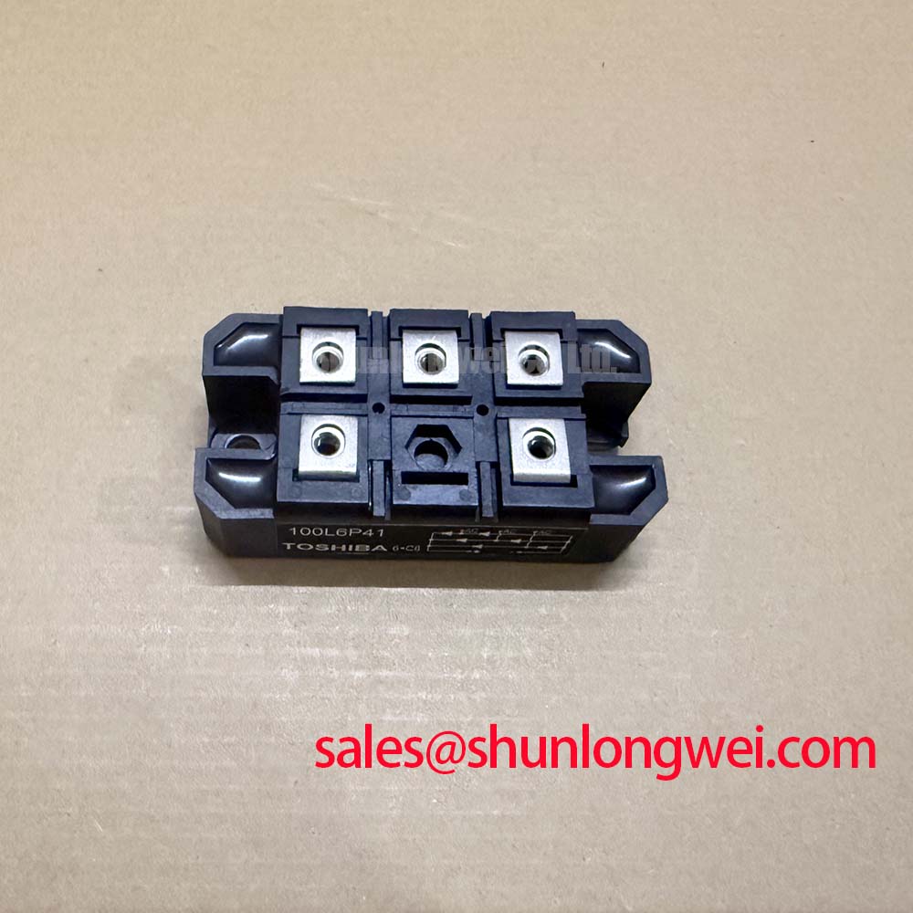
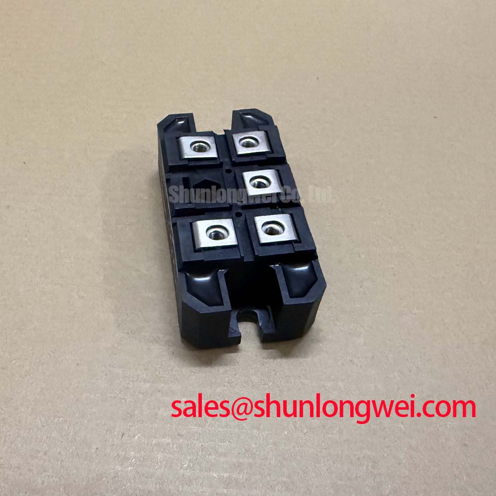
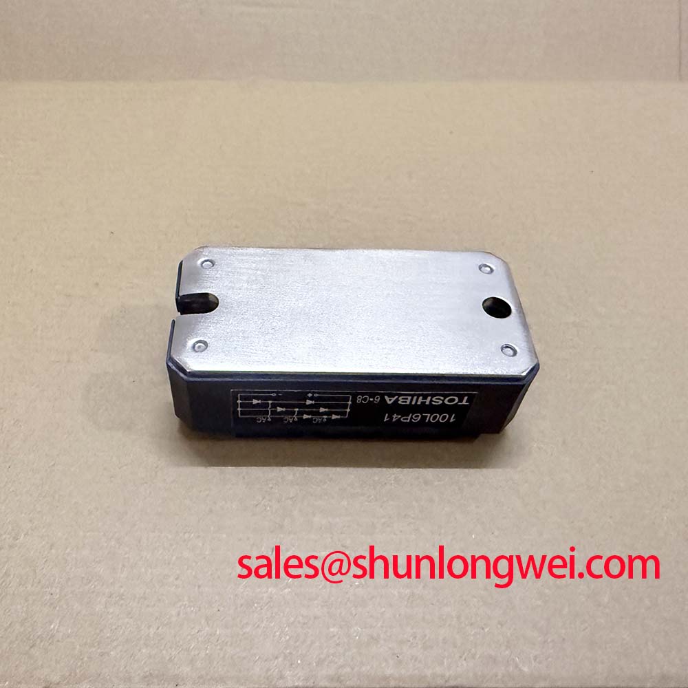
With the drive isolated, record the terminal identification, inspect the power-module body for cracks or distortion, and compare cold-state terminal impedance with a known-good phase before applying gate signals. The Toshiba 100L6P41 is identified for industrial power conversion use with a manufacturer rating of 100.0 A, a Toshiba Power Module package, and a working-voltage designation of Standard Industrial Rating. The voltage entry should be matched to the original equipment documentation before installation because the available parameter does not state a numerical voltage value.
For a heavy-duty variable-frequency AC motor drive, the practical replacement check is broader than matching the current label. Confirm the terminal arrangement, gate-driver interface, DC-link level, switching frequency, cooling assembly, protection network, and mechanical mounting pattern. A module that fits the heatsink may still require a different gate-drive or snubber arrangement.
Benchtop Waveform Tuning: Mitigating Stress via High-Frequency Commutation Loop Inductance on 100L6P41
High-frequency commutation testing should begin with the physical current loop rather than the oscilloscope settings. Keep the DC-link capacitor connection, module power terminals, and return path compact and symmetrical so that stray inductance does not create an avoidable voltage overshoot during turn-off. The peak stress can be understood from the relationship between DC-link voltage, loop inductance, and current-change rate: increasing either parasitic inductance or switching speed increases the transient component seen by the semiconductor.
Design Consideration: The proposed loop-inductance target of less than 25 nH belongs to the system layout specification, not to the published rating of the 100L6P41. Engineers should verify the actual commutation-loop inductance with the final busbar and capacitor arrangement, then confirm the resulting peak voltage during a controlled switching test. A symmetrical laminated or planar busbar can reduce magnetic-loop area, while unnecessary branch length, narrow copper necks, and offset capacitor connections can increase ringing.
When a high-frequency probe shows a narrow overshoot followed by oscillation, inspect probe-ground arrangement and measurement bandwidth before changing the gate resistor. A spring-ground connection or suitable differential probe is preferred for this measurement because a long probe lead can reproduce a false ringing signature. Compare the waveform at the module terminals rather than at a remote test point.
MOV protection is normally coordinated with the DC-link architecture, not selected from the module current rating alone. The clamping level, repetitive-energy capability, pulse energy, and upstream fuse coordination should be checked against the equipment transient environment. An MOV that clamps too aggressively can create additional leakage or thermal loading, while one with excessive clamping voltage may leave the IGBT exposed to destructive transient stress.
RC snubber selection is also system dependent. The capacitor must tolerate the repetitive pulse current and switching loss, while the resistor must absorb the associated transient energy without becoming a new heat source. Start with measured ringing frequency and terminal waveform data, then tune the network while monitoring device temperature and switching loss. Do not treat a snubber value from another inverter as a guaranteed setting for this Toshiba module.
Assembly Integrity & Layout Architecture: Eliminating Thermal Grease Pump-Out for 100L6P41
Thermal assembly quality is determined by the interface between the module base and heatsink, not by the visual amount of compound applied. Clean both surfaces using an approved process, inspect the baseplate and heatsink for burrs or visible distortion, and check that the mounting holes align without forcing the package sideways. A warped heatsink can create local pressure concentration and leave parts of the baseplate with poor thermal contact.
Apply the selected thermal interface material as a uniform, controlled film. The requested 50–80 μm interface range is a general assembly target and must be treated as a Design Consideration, not as an identified Toshiba factory specification for the 100L6P41. The final film thickness depends on surface flatness, compound rheology, mounting pressure, and the supplier’s application instructions.
Use a calibrated diagonal cross-pattern tightening sequence so that pressure develops progressively across the baseplate. The correct torque is determined by the fastener size, grade, washer arrangement, heatsink thread condition, and module mounting instructions. Excessive force can stress the substrate; insufficient force can increase thermal resistance and encourage interface movement during temperature cycling.
⚠️ Field Alert: Never insert or remove the module, gate connector, or control harness while the DC link or auxiliary gate-drive supply remains energized.
In a phase-angle or line-frequency controlled front end, ripple current and transient loading can pass through the complete power path and appear as thermal cycling at the module. Confirm that the rectifier, DC-link capacitor bank, braking path, and protective components operate together without abnormal ripple. An RC snubber may reduce high-frequency voltage movement, but it cannot correct poor heatsink contact or an undersized cooling system.
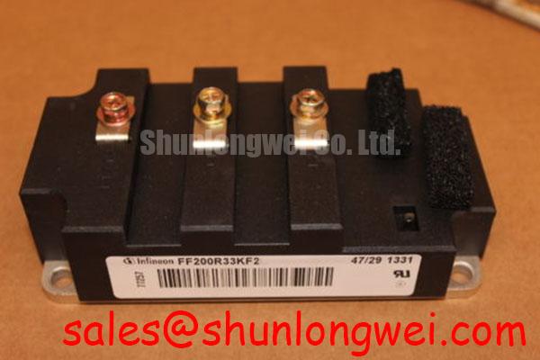
For service replacement, record the original mounting orientation and busbar position before removal. The FF400R33KF2 may be evaluated as a related replacement candidate when its electrical ratings, terminal geometry, gate-drive needs, thermal interface, and protection requirements are confirmed against the equipment design. A physical fit alone is not sufficient evidence of interchangeability.
| Evaluation item | Toshiba 100L6P41 | FF400R33KF2 evaluation point |
|---|---|---|
| Manufacturer | Toshiba | Confirm from the component documentation |
| Product category | IGBT power module | Confirm topology and semiconductor type |
| Published current value supplied for this page | 100.0 A | Confirm the applicable rated current |
| Package description | Toshiba Power Module | Confirm mounting and terminal compatibility |
| Working-voltage entry supplied for this page | Standard Industrial Rating | Confirm numerical voltage rating |
Field Diagnostics & Commissioning: Diode Reverse-Recovery Behavior in 100L6P41 Topologies
During commissioning, observe the freewheeling-diode transition at the actual module terminals and compare the current waveform with the gate-voltage waveform. Reverse-recovery behavior can produce a sharp current excursion, increased electromagnetic radiation, and additional turn-on loss in the opposing switch. A high di/dt event may also expose weaknesses in the busbar, capacitor connection, current sensor installation, or gate-driver return path.
The diode peak reverse-recovery current, commonly identified as Irrm, depends on load current, junction temperature, commutation speed, circuit inductance, and the diode’s dynamic characteristics. It should not be inferred from the 100.0 A module rating. Use a controlled test condition and record the current, collector-emitter voltage, gate voltage, and device temperature together so that the switching event can be reviewed as one system condition.
If the measured transition is excessively abrupt, the engineering response may include revisiting turn-on gate resistance, gate-loop routing, driver sink capability, or an RC damping network. These are tuning options rather than fixed installation prescriptions for the 100L6P41. The selected gate resistance must be validated against switching loss, short-circuit response, Miller coupling, and the driver’s output capability.
Diode recovery behavior in a commutation network is influenced by the complete power topology. In a motor-drive bridge, phase-leg symmetry is important because unequal stray inductance can make one leg display more severe recovery stress than another. Route gate and emitter-return conductors with a clear reference path, separate high-current commutation paths from sensitive control wiring, and inspect connector contact pressure when a waveform changes after service work.
Where electromagnetic interference rises after a module change, first correlate the change with switching edges and current-recovery timing. A small change in busbar geometry, gate-loop routing, or snubber placement can alter the measured spectrum. The external reference on Direct Torque Control for High Dynamic Industrial Induction Motor Drives provides useful context for the relationship between rapid motor-control action and inverter switching behavior, although it does not establish ratings for this module.
Transient Dynamics & Electrical Design: High-Frequency Common-Mode Bearing Current on 100L6P41
Long motor cables can behave as transmission lines when switching edges reach the cable termination, producing reflected voltage and common-mode current. The resulting terminal spike can approach twice the incident voltage in an unfavorable impedance condition. This is a system-level cable and installation effect, not a stated operating rating of the Toshiba 100L6P41.
During field commissioning, measure phase-to-phase and phase-to-ground voltage at both the inverter output and motor terminals. Compare the waveform with cable length, motor insulation condition, grounding arrangement, and carrier-frequency settings. A difference between the two measurement locations suggests that cable impedance, termination, or reflection is contributing to the observed transient. Use properly rated differential probes and maintain safe clearance around energized conductors.
Output dv/dt filters, motor chokes, and common-mode components should be selected from the motor-drive voltage, current, cable construction, switching pattern, and required control bandwidth. Their ratings must account for continuous current, transient current, heat dissipation, and the effect on motor voltage rise time. The system designer should verify that any filter does not create an undesirable resonance with the drive output and cable capacitance.
Common-mode bearing current is affected by the voltage symmetry of the three-phase output, motor frame bonding, shaft voltage paths, cable shield termination, and the installation’s protective-earth structure. When bearing-current symptoms are suspected, inspect the complete grounding path rather than attributing the condition to the IGBT module alone. The corrective action may involve cable termination, common-mode impedance, motor-side protection, or the drive’s switching profile.
For topology selection and system-level switching behavior, the reference page Resonant Topologies in Home Appliances offers additional background on how circuit topology changes current paths and transient behavior. When the 100L6P41 is considered for a heavy-duty variable-frequency AC motor drive, final validation should include the assembled busbar, protection network, cooling system, motor cable, and operating load rather than a bench component test alone.
The module’s 100.0 A value is the supplied official current parameter for product identification. MOV coordination, ITSM surge handling, transient thermal impedance, parallel-device sharing, semiconductor fuse I2t coordination, and short-circuit protection remain equipment-level design tasks requiring verification under the intended electrical and thermal conditions.