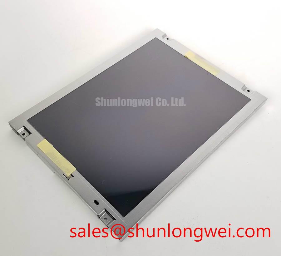
Content last revised on October 16, 2026
Preventing Localized Light Guide Plate (LGP) Compression Warp on Dark Screen Fields
Inspect bezel clearance wherever a dark patch follows an enclosure edge or mounting point. As a Design Consideration, uneven mechanical loading can alter optical uniformity in an LCD assembly. Compare the image with the surrounding trim released according to the equipment service procedure, while supporting the module securely. A repeatable change with enclosure loading helps identify an assembly-related contribution without establishing which internal optical layer is responsible.
Check the mounting drawing for support locations, bracket geometry, and fastener engagement. A screw that bottoms out can leave a bracket apparently tight while the intended support remains loose. Conversely, an uneven enclosure can transfer tightening force into the display frame. Use the equipment-approved tightening sequence and specified torque; screw diameter alone does not establish an acceptable tightening limit for this module.
Examine cable bends and insulating pads around the rear surface before refitting the enclosure. A trapped harness can create localized loading even when the front bezel appears clear. Record the location of each visible patch against the physical contact points, then repeat the same dark-field pattern after correcting the assembly. Keep viewing position and backlight settings consistent so mechanical changes remain distinguishable from observation differences.
As a Design Consideration, temperature can affect liquid-crystal response and produce slower transitions during cold startup. Compare image behavior after stabilization within the documented operating range before interpreting temporary smearing as permanent damage. Any enclosure heating arrangement should follow the equipment’s thermal design, with checks for uneven surface temperature and restricted ventilation. A heater is a system accessory requiring its own assessment.
Full-Screen Primary Color Screening: Stuck Sub-Pixels and Background Uniformity Audit
Display full-screen red, green, and blue patterns, followed by black, white, and a grayscale ramp. Keep the image source and display settings unchanged throughout the inspection. The primary colors help expose persistent sub-pixel anomalies; dark and bright backgrounds reveal different aspects of illumination uniformity. Automated optical inspection requires a defined camera arrangement and acceptance criteria; a visual bench check should record observations without implying a factory inspection classification.
As an Engineering Recommendation, distinguish persistent pixel-position defects from artifacts that change with image content, cable position, or warmup. Photograph suspicious areas using consistent exposure and viewing geometry. A bright point, fixed line, or shaded region can have several contributing causes, so its appearance alone should not determine whether the panel, cable, controller, or backlight circuit requires attention.
For a dark screen, direct an external light obliquely across the front surface and look for a faint changing image. Visible image content can help focus the next checks on illumination power, enable control, and the backlight drive path. Failure to reveal an image is inconclusive because surface reflections and ambient lighting affect visibility. Examine accessible supply and control signals using the equipment schematic and appropriate measurement practices.
Inspect a grayscale ramp for crushed near-black detail, missing tonal steps, or color imbalance. As a Design Consideration, these observations can justify checking controller configuration and accessible timing-controller supply rails. Gamma-reference measurements require circuit-specific test points and expected values. Adjusting reference circuitry to compensate for an unexplained image defect can obscure the original fault.
Compare any persistent line defect using a verified compatible signal path before assigning an internal failure mechanism. Avoid pressing the display edge to provoke a change. The The Ultimate Guide to Industrial TFT LCD Technology provides broader context for separating image generation, illumination, and integration issues during this assessment.
Interface-Aware Differential Routing and High-Frequency Jitter Assessment
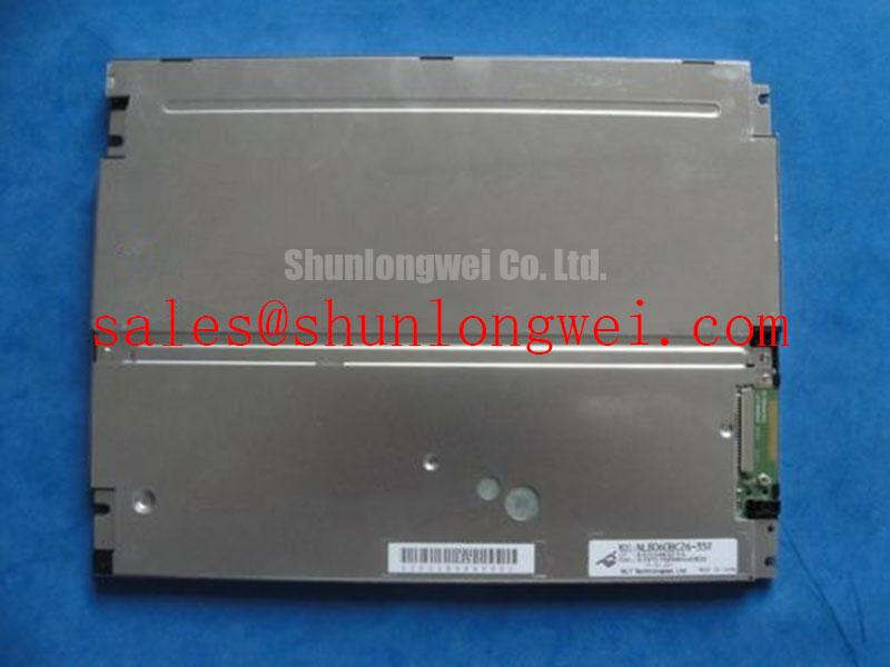
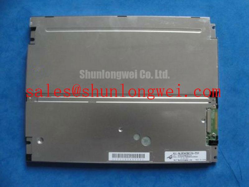
Identify the actual interface from the module connector documentation before evaluating differential routing or transmitter settings. The 100 Ω differential value in this routing topic is a general LVDS Design Consideration, not an established NL8060BC26-35AD interface specification. Single-ended TTL signals require a different assessment. Connector appearance cannot establish signaling type, supply voltage, or data mapping.
Trace power, ground, clock, and image-data connections through the equipment harness. Check connector orientation and contact numbering at both ends, especially where an adapter board is present. Field Alert: Disconnect equipment power before inserting or removing the display cable to avoid unintended signal and supply transients. Inspect latch engagement and contact condition before attempting powered measurements.
As an Engineering Recommendation, capture panel supply startup together with the relevant controller and illumination control signals. Evaluate rise behavior and sequencing against the documented requirements for the panel and host controller. Measurements at the module connection help reveal cable-related voltage drop or startup disturbance that may be absent at the power supply output.
Where LVDS is confirmed, preserve pair geometry and the intended return path through cables, connectors, and adapters. Assess clock quality and data timing at the receiver under representative operating conditions, using suitable differential probing. If the confirmed interface is TTL, examine clock-to-data timing and signal integrity against its specified thresholds. Mapping checks should follow the documented transmitter and receiver formats rather than an assumed JEIDA or VESA setting.
For intermittent corruption near switching equipment, compare the fault with machine operating state and inspect harness routing, shield termination, and chassis bonding as system-level Design Considerations. The NEC NL6448BC28-01 can serve as a separate comparison candidate during a display search, but its model designation does not establish matching resolution, dimensions, interface, or interchangeability with the NL8060BC26-35AD.
Evaluating Surface Anti-Glare (AG) and Anti-Reflective (AR) Treatments for High Ambient Readability
Evaluate readability with the intended enclosure window installed and the actual ambient light reaching the display. As a Design Consideration, reflections from that window can obscure dark image detail even when the panel produces an acceptable image on an open bench. Compare bright and dark content from the operator’s working position, then vary the illumination direction to locate dominant reflections.
Anti-glare surfaces scatter reflected light, while anti-reflective treatments reduce reflection through their optical design. These terms do not establish a particular coating, etching process, or sunlight contrast rating for the NL8060BC26-35AD. Avoid applying additional films or aggressive cleaning methods without checking compatibility with the original surface and the equipment’s optical assembly.
Assess grayscale visibility from the required operating angles rather than assuming symmetric viewing performance. Changes in apparent contrast or tonal order should be recorded with viewing direction and displayed content. General comparisons between TN and wider-viewing technologies cannot establish this module’s liquid-crystal mode or viewing cone. General industrial display context is available through Tianma industrial display information and NEC Display Solutions; integration acceptance remains specific to the module and equipment.
When evaluating replacement in a precision electronic test and measurement instrument, check whether trace colors, scale markings, and low-level indicators remain distinguishable through the finished front window. Repeat the inspection after thermal stabilization and with normal equipment activity present. Record brightness settings, viewing position, cable configuration, and any image artifacts so the service team can reproduce the acceptance check after final assembly.