
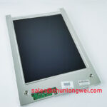
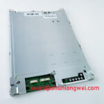
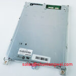
Content last revised on September 10, 2026
Aluminum Heat Spreader Sizing and Thermal Interface Placement along Narrow Display Edges
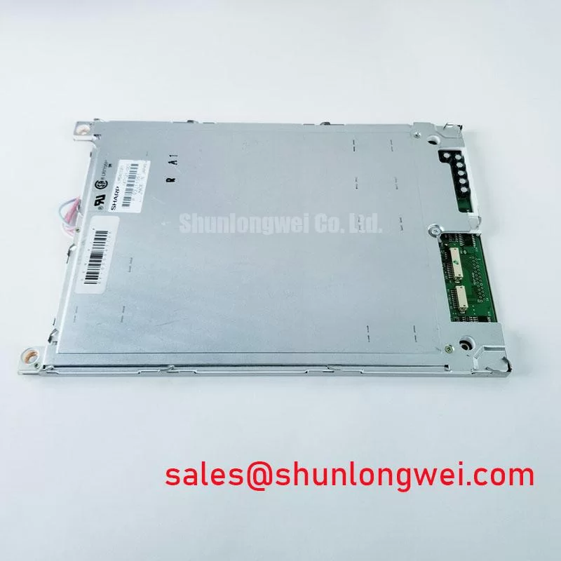
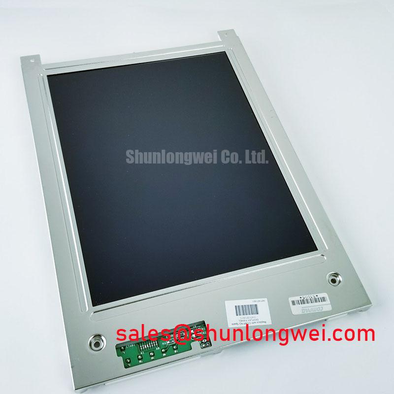
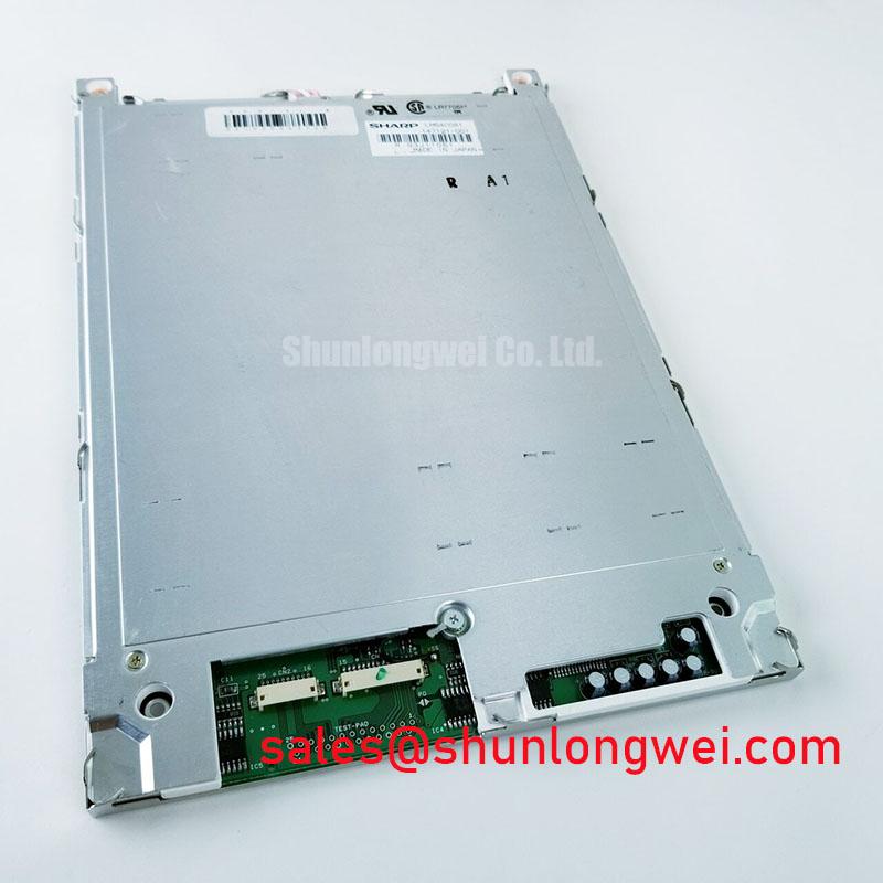
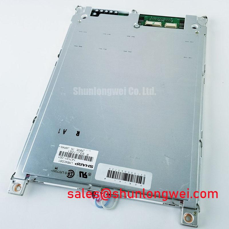
Inspect the rear frame, edge rails, cable exit area, and enclosure contact points before selecting any thermal spreader. An aluminum rail can help distribute heat along a narrow display edge, but it should not be treated as an LM64C081 factory specification or attached in a way that transfers concentrated mechanical load into the glass. The practical objective is to reduce localized temperature differences while preserving the panel’s designed mounting condition.
This is particularly relevant in sealed industrial HMI enclosures and in operator displays evaluated for heavy mining shovel or earthmoving equipment telematics. Such installations can combine direct solar loading, cabinet heat, vibration, and restricted airflow. Designers should map the actual heat sources around the display, backlight electronics, processor board, and power conversion stage before deciding whether an edge spreader is necessary. The final arrangement should be validated by temperature measurement during representative operation rather than selected from a generic rail dimension.
The thermal interface should remain even and compliant. A rigid insert, an uneven adhesive layer, or an over-tightened bezel can introduce local stress, visible non-uniformity, or optical pressure marks. Use the existing mounting points where possible, keep the interface clear of the active viewing area, and confirm that the spreader does not obstruct ventilation or press against the FPC. Any thermal compound, pad, or adhesive should be selected for compatibility with the enclosure materials and verified across the equipment’s actual temperature range.
Cold-start behavior also requires system-level verification. Liquid crystal response can become slower at low ambient temperature, and the resulting image lag may be confused with a timing, power, or signal fault. Allow the panel to reach a stable thermal condition while monitoring the display controller output, backlight enable behavior, and image refresh. If a heater strip is used in the host equipment, its control profile should be determined by the enclosure designer using measured panel temperature and condensation risk. The supplied data does not establish a specific heater setting or low-temperature response time for LM64C081.
When the panel is being compared with another display in the same repair program, engineers may review LM64P10 as a separate Sharp display option. It should be evaluated independently for connector position, timing, optical characteristics, mounting dimensions, and backlight requirements rather than treated as a direct replacement without verification.
Super IPS or MVA Wide Symmetric Viewing Cone for Multi-Angle Consoles
Do not infer the viewing technology or viewing-angle performance of LM64C081 from the product category alone. The supplied factory information confirms a Sharp TFT LCD Display Module, but it does not provide a verified 85/85/85/85 viewing-angle specification, Super IPS designation, MVA designation, grayscale behavior, surface treatment, or contrast data. These values must be taken from the correct panel revision documentation before the unit is approved for a multi-angle console.
In a cab display or service console, evaluate the actual operator sight lines rather than relying only on a nominal viewing-angle figure. Check the image from the seated, standing, and side service positions under the real ambient illumination. Anti-glare treatment can improve readability under bright light, but it can also alter perceived sharpness, contrast, and surface cleaning behavior. The system owner should confirm whether the existing enclosure window, protective cover, and lighting arrangement were designed around the original optical stack.
The video path should be inspected as a complete chain. Confirm the host controller output standard, connector pinout, signal polarity, pixel clock arrangement, data enable behavior, and power sequencing against the source documentation. Where TTL or LVDS signaling is present in the host design, the transmitter and receiver timing should be checked with an oscilloscope or suitable logic measurement method. Clock jitter, data hold behavior, cable routing, grounding, and connector retention are system characteristics; they are not established LM64C081 factory parameters in the supplied information.
Intermittent image noise, missing data, or unstable startup should be approached as a structured signal-path investigation. Compare the suspect display with a known-good path, inspect the cable and connector for contamination or incomplete locking, and confirm that the controller’s timing profile matches the original configuration. Avoid assigning a single cause from the appearance of the screen alone, because a display symptom can also result from power sequencing, cable integrity, controller configuration, or enclosure interference.
Where the display is paired with a separate backlight or display support assembly, the surrounding topology should be documented before replacement. The Sharp LMS700KF01-001 page may be useful as a related display solution reference, but compatibility must be established from the equipment wiring, connector definition, and original service documentation.
Thermal Cycling Degradation of Polarizer Adhesives and Sealant Gasket Integrity
During preventive maintenance, inspect the perimeter seal, bezel compression, display window, and gasket contact surface for gaps, lifting, abrasion, or hardened sections. A gasket that no longer contacts evenly can permit dust or moisture ingress and can also create uneven pressure around the display. The inspection should include the cabinet mating surface, because a distorted panel opening may place more stress on one edge of the LCD than on another.
Thermal cycling can produce differential movement between the display assembly, bezel, enclosure, adhesive layers, and cable retention hardware. The supplied factory data does not specify polarizer adhesive life, epoxy composition, sealant construction, thermal-cycle qualification, or a guaranteed industrial temperature range for LM64C081. These subjects therefore remain design and maintenance considerations, not confirmed model ratings.
For equipment that experiences cold storage, rapid warming, or high enclosure temperatures, designers should assess condensation separately from normal operating temperature. A controlled warm-up, suitable enclosure sealing, and a means of limiting moisture accumulation may be required by the host system. Inspect the display after environmental exposure for haze, uneven brightness, edge lifting, image retention, or changes in cable contact. Such observations should be recorded with cabinet temperature and operating conditions so that the service decision is based on repeatable evidence.
The FPC should be routed with a gradual bend and protected from rubbing, sharp edges, repeated movement, and clamp pressure. Do not fold the cable at the connector exit or use it as a retaining strap for the panel. The connector lock should be fully engaged and checked after vibration testing or cabinet service. The original connector type, contact assignment, and allowable bend condition must be verified from the applicable Sharp documentation because these details are not included in the supplied parameter set.
Signal integrity also depends on the host board and cable assembly. If a high-speed differential interface is used, the system designer should preserve the intended pair routing, reference structure, and termination arrangement, then verify the signal at the display connector under operating temperature and vibration conditions. A measured impedance target or skew limit should only be applied when it is defined by the actual interface specification. The LM64C081 information supplied here does not authorize a particular differential impedance or skew budget.
⚠️ Maintenance Note: Check the cabinet airflow path and gasket seating during scheduled service, and disconnect power before removing or inserting the display cable.
For background on panel selection, interface planning, and common industrial TFT LCD integration issues, consult The Ultimate Guide to Industrial TFT LCD Technology. It should support engineering review, while the exact LM64C081 replacement decision still depends on the original panel documentation and host equipment records.
Suppressing Acoustic Capacitor Buzz and EMI Emissions across PWM Frequencies
Before diagnosing a dark screen, separate the display image path from the backlight path. Confirm the controller output, panel power behavior, backlight enable signal, and driver response independently. A backlight fault can leave the image data path operating normally, while a controller or cable problem can produce a dark or unstable image even when the lighting circuit is functional.
The supplied factory information does not confirm whether this LM64C081 configuration uses a CCFL assembly, an LED backlight, an integrated driver, or a separate constant-current driver. The system integrator should verify the required backlight architecture from the original panel documentation. Do not substitute a CCFL inverter or LED driver based only on connector similarity, since ignition requirements, current regulation, protection behavior, and dimming control can differ substantially.
When a separate LED driver is confirmed, inspect its open-load and short-load protection behavior using the manufacturer’s driver documentation. A driver fault output, if provided, should be checked at the controller interface while monitoring current and voltage under controlled test conditions. Repeated protection cycling may arise from the driver, wiring, connector contact, backlight assembly, or control signal, so the diagnostic record should identify which section was measured rather than assigning the symptom to the LCD module alone.
PWM dimming should be evaluated for visible modulation, camera banding, audible noise, and interaction with the host controller. The requested 200 Hz to 1 kHz range is an application test range, not a verified LM64C081 factory parameter. The final frequency, duty-cycle limits, dimming method, and control voltage must be selected from the actual backlight driver specification and validated at the required brightness levels. If acoustic capacitor buzz or EMI appears, inspect switching-loop layout, cable placement, grounding, enclosure resonance, and driver operating conditions.
Claims such as a 50,000-hour half-brightness life or a guaranteed MTBF cannot be assigned to LM64C081 from the supplied factory data. LED lifetime depends on junction temperature, regulated current, optical environment, thermal transfer, and the specific backlight assembly. Any life estimate used in a maintenance plan should come from the applicable Sharp panel or backlight datasheet, an authorized qualification report, or a documented system test. The display module itself should not be represented as independently certified for complete equipment EMC compliance; the finished enclosure and wiring remain responsible for system-level evaluation.