

Content last revised on September 10, 2026
Dynamic Contrast Ratio Stabilization and Liquid Crystal Temperature Tracking
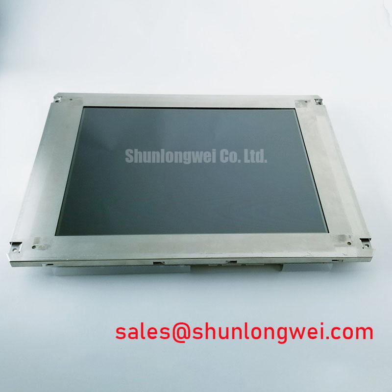
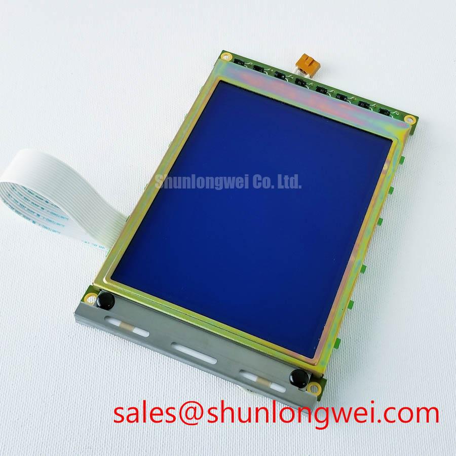
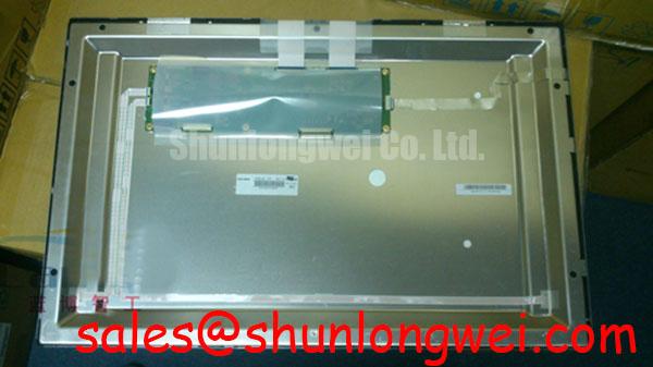
Begin a replacement assessment by checking the installed panel label, connector orientation, mounting interface, and visible display condition before applying power. The G260JJE-L07 is identified in the supplied factory context as an AUO TFT LCD Display Module for industrial LCD and HMI applications, with its specification status recorded as Official Factory Spec Verified. The available product record does not provide a complete electrical timing table, optical table, dimensional drawing, or confirmed backlight specification, so those values should be verified against the original panel documentation before procurement or installation.
| Item | Recorded information |
|---|---|
| Model | G260JJE-L07 |
| Manufacturer | AUO |
| Product category | Industrial Grade LCD/HMI Panel |
| Module type | TFT LCD Display Module |
| Specification status | Official Factory Spec Verified |
| Primary evaluation use | Industrial display replacement and HMI integration assessment |
For repair engineers, the most important first decision is physical and electrical compatibility rather than screen appearance alone. Check the active area, bezel opening, mounting-hole pattern, connector position, cable bend radius, signal interface, power entry, and backlight control arrangement. The system integrator should verify the required supply voltage from the original panel documentation. The supplied record does not confirm whether the installed system uses LVDS, TTL, a particular JEIDA or VESA mapping, or a defined LED driver interface.
Contrast complaints should be assessed after separating panel behavior from the host display controller. Record the image condition at startup, after thermal stabilization, and during a controlled change in ambient temperature. A grayscale ramp, dark-field image, and representative ultrasound or surgical-navigation image can reveal whether the issue is related to grayscale inversion, viewing angle, backlight regulation, timing configuration, or enclosure reflections. These observations are useful during a G260JJE-L07 replacement check, but they do not establish an AUO performance rating unless the value appears in the applicable panel specification.
TN, IPS, and MVA technologies can show different viewing-cone behavior. A symmetric viewing-angle claim such as 85° in four directions belongs to a specific optical datasheet and should not be transferred to this model without documentary confirmation. The same principle applies to dynamic contrast ratio. The G260JJE-L07 record supplied here identifies the module category, but it does not confirm a contrast-ratio value, panel technology, surface treatment, or viewing-angle specification.
Under sub-zero conditions, liquid-crystal response can become slower and grayscale transitions may appear uneven. A heater strip may be considered in the enclosure design when the equipment must start in a cold environment, but heater placement, control thresholds, insulation, and warm-up timing are system-level decisions. Engineers should monitor the panel surface temperature, image response, supply stability, and controller timing together rather than attributing every cold-start artifact to the LCD cell.
Surface reflections also affect perceived contrast in high-illumination rooms. Anti-glare treatment can reduce reflected light, although it may influence sparkle, haze, sharpness, and cleaning behavior. If the panel is considered for a high-precision surgical or ultrasound diagnostic display, the integrator should compare the installed optical stack under the actual procedure-room lighting arrangement. A direct-sunlight contrast value or a greater-than-500:1 result is not confirmed for this model in the supplied factory data.
Chassis Fastener Loading and Optical Mura Control
Before mounting the G260JJE-L07, compare the replacement module with the original chassis drawing. Confirm the outer bezel envelope, active-area alignment, connector clearance, cable exit, and contact points around the display perimeter. Excessive or uneven frame loading can create localized optical non-uniformity, pressure marks, or dark-field mura. These effects depend on the host bezel, support surfaces, gasket behavior, and fastening sequence, not on the model number alone.
A cross-pattern tightening sequence is a useful Design Consideration for distributing mechanical load across a display frame. The supplied engineering brief mentions an M3 torque range of 0.35 to 0.45 N·m, but this must be treated as a general integration reference rather than an official G260JJE-L07 factory requirement. The correct limit remains determined by the chassis material, fastener design, washer or spacer arrangement, and the applicable mechanical drawing. Engineers should validate the assembled panel using a dark image and a uniform gray field after fastening.
Connector strain deserves the same attention as screw loading. A cable that is forced against the bezel or folded close to its connector can introduce intermittent image loss, local pressure, or long-term contact stress. Route the cable according to the original equipment geometry, preserve clearance from sharp edges, and inspect the latch or retention feature before closing the enclosure. Do not insert or remove the display cable while the host system is energized.
Signal compatibility should be confirmed at the interface level. For an LVDS design, review differential-pair allocation, clock polarity, lane order, termination arrangement, and the selected JEIDA or VESA data format. For a TTL design, verify the pixel clock, data hold relationship, synchronization signals, and logic-level requirements from the original controller documentation. The available product record does not confirm the interface type or timing values for the G260JJE-L07, so a replacement should not be approved from connector appearance alone.
When an alternative screen is being evaluated, the M185XW01 VE may be reviewed as a separate same-size or same-resolution sourcing reference where its own published interface and mechanical data match the equipment. It should not be treated as a direct substitute until the active area, resolution, connector pinout, signal format, backlight system, and mounting dimensions have been checked.
Backlight Drive, Acoustic Noise, and EMI Evaluation
Display failures that appear as a dark screen should be divided into image-generation faults and backlight faults. With suitable electrical safety controls, inspect whether image data is present, whether the panel enable sequence is correct, and whether the backlight driver receives its expected control signal. A dark image with a visible raster under appropriate inspection may point toward a backlight or driver path, while a completely inactive image requires checks of power, interface signaling, and host timing. These observations are diagnostic directions, not single-cause conclusions.
The supplied record does not confirm whether the G260JJE-L07 uses an LED or CCFL backlight, nor does it specify a PWM frequency, dimming ratio, ignition voltage, acoustic-noise limit, or driver topology. Do not apply a CCFL ignition value such as 1500 to 1650 Vrms, a 1000:1 LED dimming claim, or a defined PWM operating window to this model without the matching AUO documentation and the original equipment service information.
For an LED implementation, the system designer should verify constant-current regulation, enable polarity, dimming method, minimum operating duty, and open-load or short-load behavior. PWM harmonics can couple into image cables, touch interfaces, microphones, and enclosure wiring. Keep the backlight power loop physically separated from sensitive signal paths where the chassis permits, and verify radiated and conducted behavior in the completed equipment. A display module by itself cannot be described as independently compliant with an entire system EMC standard.
For an older CCFL-based system, high-voltage routing, insulation spacing, lamp-current control, inverter noise, and acoustic vibration require evaluation at the assembly level. The product record supplied for the G260JJE-L07 does not confirm such a configuration. The integrator should verify the required backlight technology from the original panel documentation instead of fitting a driver based only on connector similarity.
When investigating interference, use a known-good signal path and observe the pixel clock, data activity, backlight control waveform, and supply behavior with suitable measurement equipment. The reference article on drift velocity and carrier mobility provides general semiconductor background, but it is not a G260JJE-L07 optical, timing, reliability, or EMC specification.
Constant Luminance Control and Backlight Reliability Verification
Long-term brightness assessment should begin with a baseline measurement taken at the intended display setting and enclosure condition. Repeat the measurement after thermal stabilization and compare the center and edge regions of the screen. This helps distinguish driver regulation, thermal gradients, optical non-uniformity, and panel aging. The supplied factory information does not state an L70 or B50 rating, LED half-life, MTBF, brightness-decay curve, or guaranteed operating-hour value for the G260JJE-L07.
Aluminum spreader rails, edge supports, or other thermal provisions may be considered when a system shows a localized hot spot near the display edge. Their effectiveness depends on contact pressure, thermal interface construction, airflow, enclosure materials, and the actual backlight architecture. Avoid claiming that a particular rail size will prevent optical yellowing unless the complete mechanical and thermal design has been tested. The system engineer should verify luminance uniformity, surface temperature, driver current stability, and image quality under the equipment’s real duty cycle.
For medical display equipment such as surgical-navigation monitors or ultrasound diagnostic terminals, compatibility review should also cover image-processing latency, grayscale presentation, cleaning procedures, enclosure sealing, cable retention, and the host system’s power sequencing. These are system requirements and should not be inferred from the TFT LCD module category. Safety certification, clinical performance, EMC approval, and insulation reliability belong to the finished equipment and its compliance program, not automatically to the display module.
During a replacement trial, document the original panel’s connector pinout, mounting references, backlight behavior, startup sequence, and display settings before removal. Compare the replacement under identical controller settings, then verify image geometry and brightness after the chassis is fully secured. For broader enclosure, interface, and harsh-environment integration considerations, engineers can consult Industrial Display & HMI Solutions.
💡 Pro Tip: Keep LVDS differential pairs controlled as a matched signal group and verify clock and data integrity at the receiving interface rather than judging compatibility from the connector shape.