


Content last revised on May 3, 2026
7MBI50N-120 IGBT: Efficiency in 7-in-1 Power Conversion
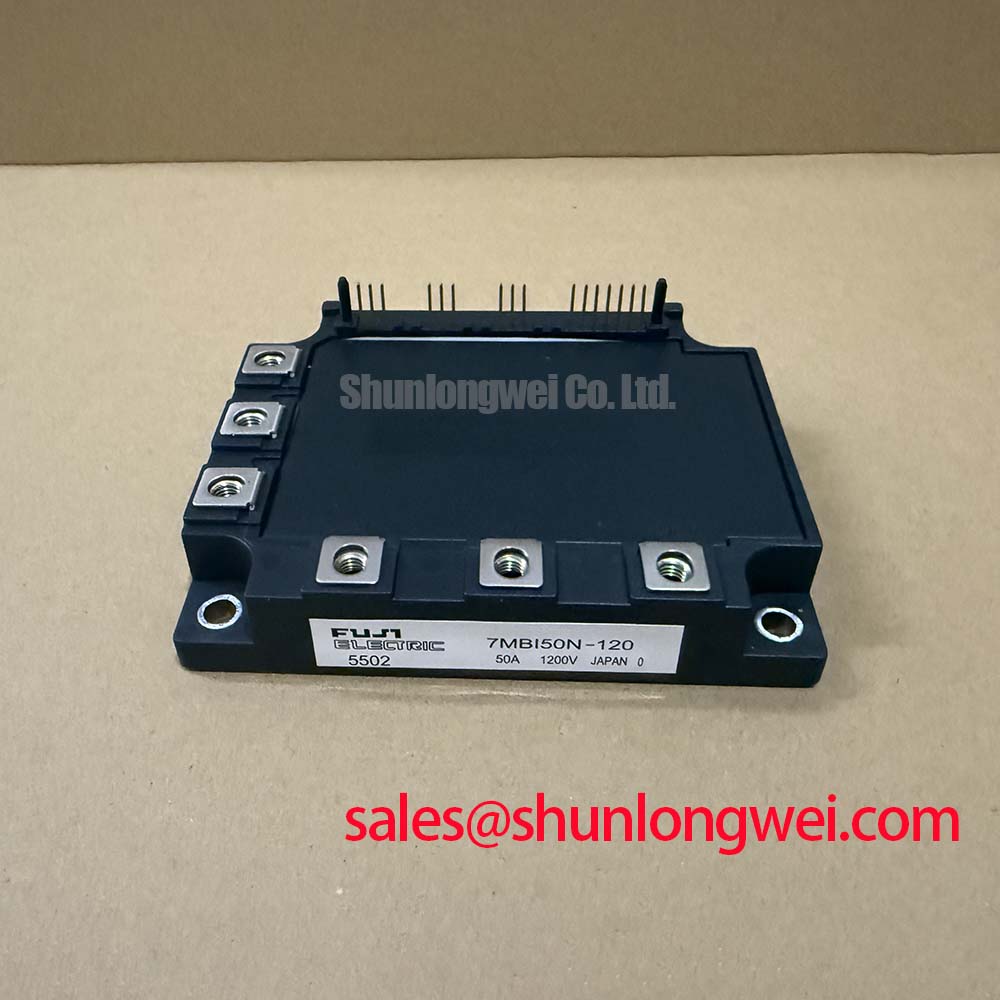
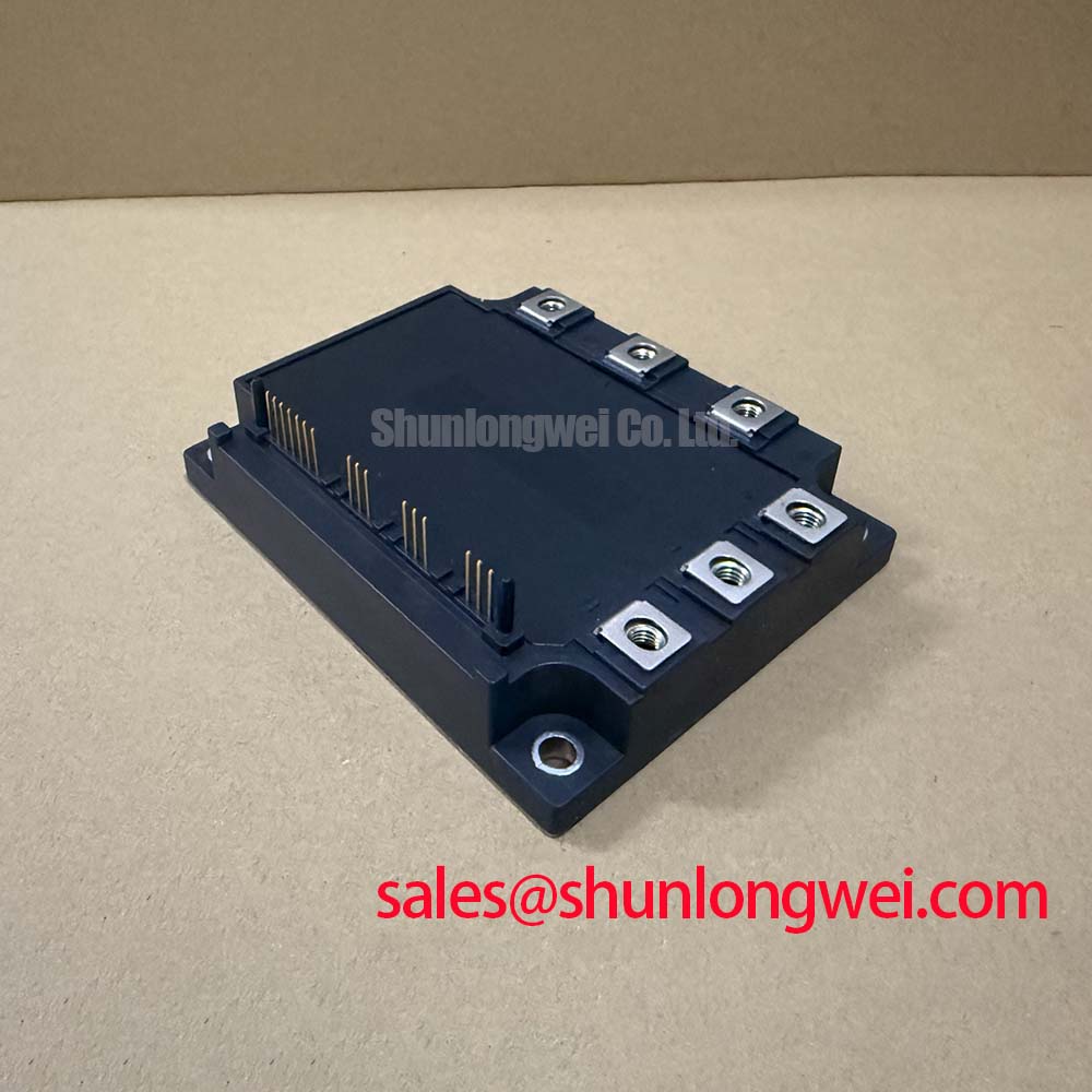
The Fuji Electric 7MBI50N-120 is a 7-in-1 IGBT module engineered for exceptional switching efficiency in compact power systems. Delivering benchmark performance with specifications of 1200V | 50A | VCE(sat) 2.7V, this module integrates a full three-phase inverter, brake chopper, and a three-phase rectifier bridge. Its key benefits include minimized conduction losses and simplified thermal design. For engineers evaluating power stages for variable frequency drives, the module's low saturation voltage directly translates to reduced heat generation under load, enabling higher power density and improved system reliability.
Value Proposition in Demanding Power Applications
The Fuji Electric 7MBI50N-120 is engineered for power conversion systems where efficiency and compact design are critical operational drivers. Its integrated 7-in-1 configuration, combining a three-phase inverter, brake unit, and converter bridge, makes it a cornerstone for small to medium-power motor drives and general-purpose inverters. The module's design is particularly advantageous in applications like HVAC systems, pump and fan controls, and other automated industrial machinery. By consolidating multiple power stages into a single package, it reduces assembly complexity and simplifies the overall system layout. For systems that need to handle higher power levels, the 7MBR75VB120-50 provides a higher current rating within a similar functional architecture.
What is the main advantage of the 7MBI50N-120's VCE(sat)? Its low collector-emitter saturation voltage minimizes heat, improving system efficiency.
Strategic Advantage: Consolidating Power Stages for Modern Industrial Drives
In the current industrial landscape, there is a significant push towards developing more compact, energy-efficient, and cost-effective motor control systems. The Fuji Electric 7MBI50N-120 directly addresses this trend by offering a highly integrated power solution. The traditional approach of using discrete components for the rectifier, brake chopper, and inverter stages requires more PCB space, increases assembly time, and complicates thermal management. This module’s 7-in-1 topology streamlines the design process, enabling engineers to develop smaller and more reliable Variable Frequency Drives (VFDs). This consolidation contributes to a lower total cost of ownership, not just through reduced component count, but also through simplified supply chains and manufacturing processes—a crucial factor for OEMs scaling production.
Comparative Data for Informed Decision-Making
When evaluating power modules, a direct comparison of key parameters provides the necessary data for an informed engineering decision. The table below presents the specifications for the 7MBI50N-120 alongside another component from a similar class. This data is intended to support system designers in their component selection process by highlighting critical performance metrics.
| Parameter | Fuji Electric 7MBI50N-120 | Fuji Electric 7MBR50SB120-50 |
|---|---|---|
| Configuration | 7-in-1 (Three-Phase Inverter + Brake + Three-Phase Converter) | 7-in-1 (Three-Phase Inverter + Brake + Three-Phase Converter) |
| Voltage (Vces) | 1200V | 1200V |
| Current (Ic) | 50A | 50A |
| VCE(sat) (Typ @ Ic, 25°C) | 2.2V | 1.7V |
| Package | M711 | P626 |
Note: This comparison is based on publicly available datasheet values. Engineers should consult the official datasheets for complete and application-specific details.
Unpacking the Core of Switching Efficiency
A granular analysis of the 7MBI50N-120's electrical characteristics reveals a design focused on minimizing power loss, a central challenge in power electronics design. The two primary contributors to inefficiency in an IGBT are conduction losses and switching losses. The module's low VCE(sat) of 2.7V (max) directly reduces conduction losses—the heat generated while the switch is on. Think of VCE(sat) as a form of electrical friction; the lower the value, the less energy is wasted as heat during operation. This characteristic is a direct result of Fuji Electric's planar IGBT structure, optimized for high current density with minimal voltage drop. This efficiency is critical for designers aiming to meet stringent energy standards and enhance the long-term reliability of their systems. For further reading on IGBT principles, explore this guide on IGBT working principles.
Why is low switching energy important? It allows for higher frequency operation without excessive heat, enabling smaller magnetics.
For motor drives operating between 2 and 15 kHz, the 7MBI50N-120's switching performance is the optimal choice for balancing efficiency and acoustic noise. The module's datasheet provides detailed turn-on (Eon) and turn-off (Eoff) energy specifications, allowing engineers to precisely calculate and manage thermal loads, which is a fundamental aspect of robust IGBT thermal performance.
Key Specifications and Their Engineering Significance
The performance of the 7MBI50N-120 is defined by several key parameters that directly impact its application suitability. Understanding these values is crucial for accurate system modeling and design validation. For a complete list of specifications, please Download the Datasheet.
| Parameter | Value | Engineering Meaning |
|---|---|---|
| Collector-Emitter Voltage (Vces) | 1200V | Provides a substantial safety margin for applications running on 400V to 575V AC lines, protecting against transient voltage spikes. |
| Collector Current (Ic) | 50A (at Tc=80°C) | Defines the module's continuous current handling capability under specified thermal conditions, suitable for motors up to approximately 22 kW. |
| Collector-Emitter Saturation Voltage (VCE(sat)) | 2.7V (Max) | Directly correlates to conduction losses. A lower value signifies higher efficiency and less heat generated during operation. |
| Total Power Dissipation (Pc) | 260W (per IGBT) | Indicates the maximum amount of heat the device can dissipate. This figure is critical for designing an effective thermal management system. |
| Operating Junction Temperature (Tj) | +150°C (Max) | Sets the upper thermal limit for the semiconductor junction, a key parameter for ensuring long-term operational reliability. |
Frequently Asked Questions (FAQ)
What is the primary benefit of the 7-in-1 configuration in the 7MBI50N-120?
The integrated design significantly simplifies system assembly and layout by combining the input rectifier, brake chopper, and output inverter into a single, compact module. This reduces component count, minimizes wiring complexity, and streamlines thermal management, leading to a smaller overall system footprint and potentially lower manufacturing costs.
How does the VCE(sat) of the 7MBI50N-120 impact inverter design?
With a maximum VCE(sat) of 2.7V, the module keeps conduction losses low. For a design engineer, this means less heat is generated for a given current, which can lead to the use of a smaller, more cost-effective heatsink. It also improves overall system efficiency, a key requirement for modern, energy-conscious applications like variable frequency drives.
Is this module suitable for high-frequency switching applications?
The 7MBI50N-120 uses Fuji's NPT (Non-Punch-Through) planar IGBT technology, which is optimized for a balance between low conduction losses and switching performance. While it performs exceptionally well in typical motor drive frequencies (e.g., 2-15 kHz), for applications requiring very high frequencies (above 20 kHz), designers should carefully analyze the switching losses (Eon, Eoff) detailed in the datasheet to ensure thermal stability.
What considerations are necessary for the gate drive circuit?
A stable gate drive circuit is essential for reliable IGBT operation. The datasheet specifies a recommended gate-emitter voltage (Vge) of +15V for turn-on and a range of -5V to -15V for turn-off. Using a negative voltage for turn-off is crucial to prevent unintended turn-on due to noise or the Miller effect, thereby ensuring robust performance in electrically noisy environments.
What is the function of the built-in thermistor?
The integrated NTC thermistor provides a means for real-time temperature monitoring of the module's baseplate. This allows the system's control logic to implement over-temperature protection, which is a critical safety feature that can prevent catastrophic failure and significantly enhance the long-term reliability of the power converter.
Design and Integration Outlook
For engineers tasked with developing next-generation motor drives and power converters, the Fuji Electric 7MBI50N-120 offers a compelling pathway to achieving higher power density and efficiency. The key to maximizing its potential lies in a holistic design approach. Future optimization efforts should focus on co-designing the gate drive and thermal management systems to fully exploit the module's low-loss characteristics. By leveraging its integrated nature, designers can not only simplify their current projects but also build a scalable and reliable power platform for future innovations in industrial automation.