Content last revised on September 27, 2026
6MBI35S-140 Electrical Identity and Bench Verification
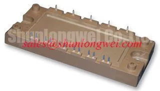
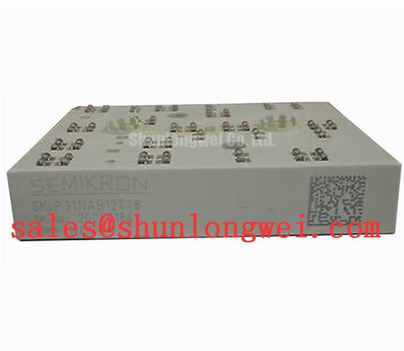
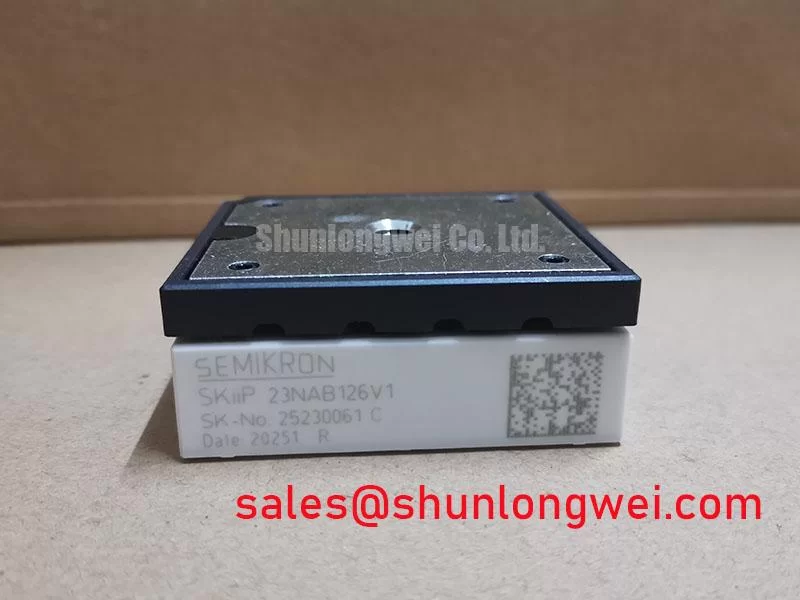
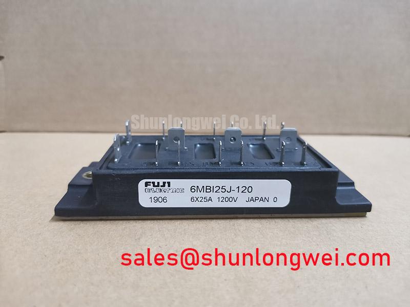
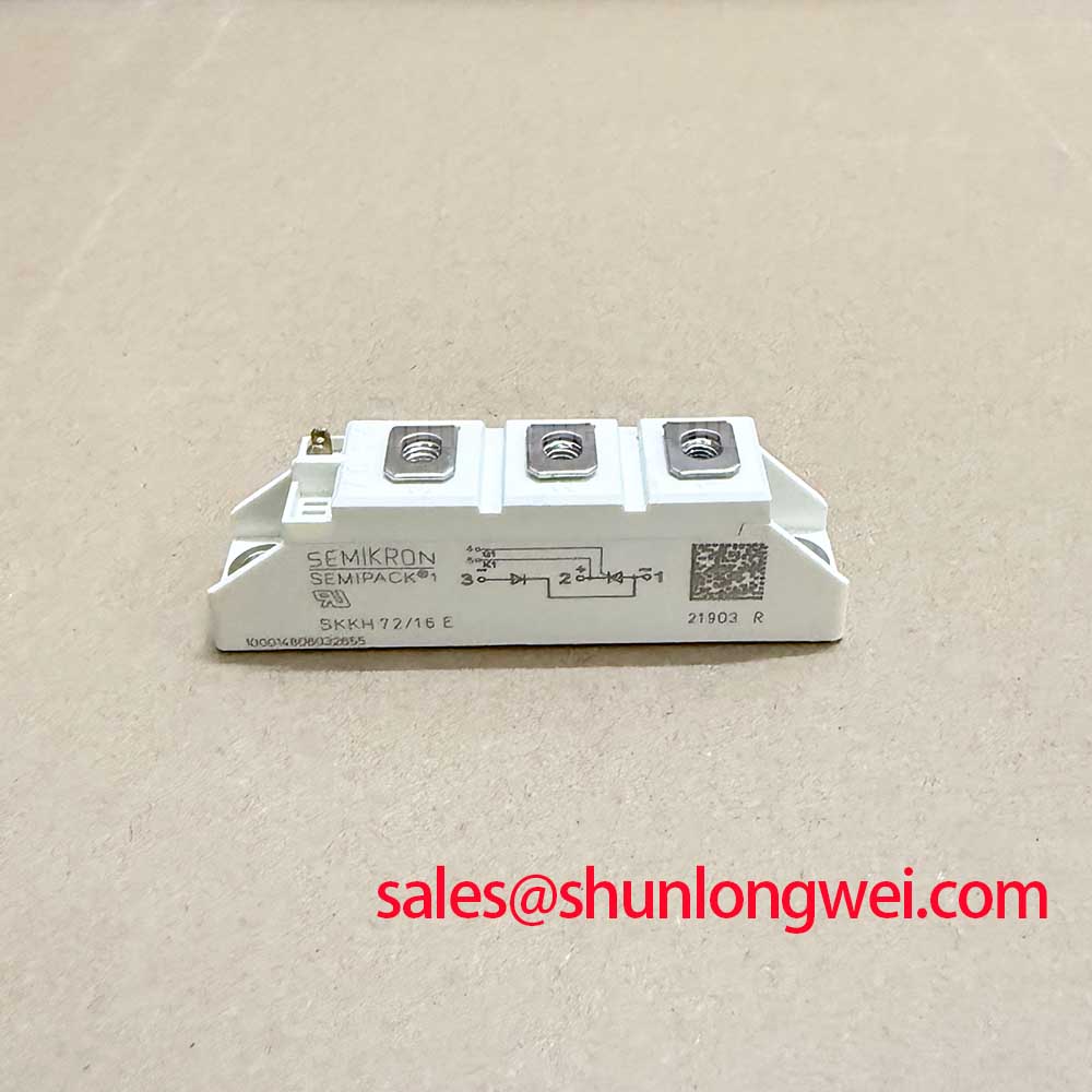
Begin the service inspection by isolating the drive, confirming the nameplate boundary, and checking the module body for cracks, loosened terminals, contamination, or mechanical stress before applying any test voltage. The 6MBI35S-140 is a Fuji Electric IGBT Module rated at 1400 V and 35.0 A, with a Module package designation.
| Parameter | Specified Value | Classification |
|---|---|---|
| Manufacturer | Fuji Electric | Product identification |
| Model | 6MBI35S-140 | Product identification |
| Rated voltage | 1400 V | Manufacturer rating |
| Rated current | 35.0 A | Official supplied specification |
| Package | Module | Official supplied specification |
For a removed unit, use a controlled, current-limited meter procedure to compare terminal resistance and diode conduction behavior with a known-good reference from the same circuit. A meter reading alone does not establish switching health, insulation condition, or dynamic current capability. The original gate and power-terminal identification must be checked against the equipment documentation before any replacement is connected.
🔧 Field Alert: Disconnect the DC bus and verify the stored energy has fallen to a safe service condition before removing terminals or handling the module.
Transient Dynamics & Electrical Design: Suppression of 2x V_DC Voltage Doubling on 6MBI35S-140
Long motor leads can create impedance mismatch between the inverter output and the motor input. Reflections can add to the switching waveform, producing terminal overshoot that may approach a multiple of the local DC bus voltage under unfavorable cable, termination, and switching conditions. This is a system-level effect, not an additional rated-voltage value for the 6MBI35S-140.
Design Consideration: When this module is evaluated in a light industrial automation inverter or multi-joint robotic articulator, the engineer should inspect the complete motor-cable route, shield termination, output filter arrangement, and switching waveform at the module terminals. An oscilloscope with a suitably rated differential probe can help distinguish a genuine device-side overshoot from probe-loop pickup or an incorrect measurement reference.
Output chokes, dv/dt filters, or motor-end filtering may be considered where the measured waveform exceeds the system designer’s voltage and insulation limits. Their values and placement depend on motor capacitance, cable length, switching frequency, control response, and drive topology. The correct selection must therefore be validated through switching tests rather than assigned from the module’s current rating alone.
Keep the high-current commutation path physically compact, separate signal wiring from power conductors, and maintain the creepage and clearance required by the equipment insulation system. The Fuji Electric V-Series IGBT Application Manual provides application-level reference material for evaluating switching behavior, gate control, and protection conditions. The system integrator should verify the applicable information for this exact device and circuit.
6MBI35S-140 Circuit Protection & Reliability: Commutation Loop Inductance
During turn-off, stray commutation inductance interacts with current change and can raise the collector-emitter voltage above the steady DC-link value. In engineering terms, the transient contribution follows the relationship between loop inductance and di/dt; the resulting peak must be checked against the device rating and the measured switching waveform. This is an engineering calculation and cannot be inferred from the stated 1400 V rating alone.
Use a symmetrical planar busbar arrangement where practical, place the DC-link decoupling close to the switching path, and avoid routing the return conductor far from its corresponding forward path. Snubber capacitors, clamps, or other protection elements should be selected from measured overshoot, pulse energy, repetition rate, and thermal conditions. Their values remain system-determined.
For parallel modules, equal electrical path length and comparable thermal conditions are important design considerations. Static sharing can be influenced by the temperature behavior of conduction voltage and by differences in busbar resistance, gate-loop impedance, and cooling. Do not assume that identical part numbers alone guarantee balanced dynamic current. Capture current and voltage waveforms in the intended operating arrangement and review the result under both low-load and high-load conditions.
The gate loop deserves the same discipline as the power loop. Keep the gate-drive return separate from high-current emitter paths unless the manufacturer’s terminal arrangement explicitly requires another method. A shared return can convert power-loop voltage movement into false gate feedback and intermittent protection trips. Any auxiliary emitter or control terminal must be confirmed from the original Fuji Electric documentation before wiring. The related 6MBI100L-060 may appear in associated converter topologies, but its electrical role and ratings must not be substituted for those of this module.
Preventing Spurious Faults: Regenerative DC-Bus Voltage Surge Dissipation Guidelines for 6MBI35S-140
When a motor decelerates, returned mechanical energy can raise the DC-link voltage. A drive may use a braking chopper and resistor, an active front end, or another energy-management method. The 6MBI35S-140 should not be assumed to include a braking function merely because it is an IGBT module; the complete schematic must identify the switching device, sensing circuit, clamp path, and resistor bank.
Engineering Recommendation: Determine the regenerative energy from the actual load inertia, speed profile, stopping interval, duty cycle, and allowable DC-link range. Then verify the selected braking branch for pulse energy, average thermal loading, switching stress, fault behavior, and resistor enclosure temperature. The chopper threshold and protection response are controlled by the drive system and should be validated during a controlled deceleration test.
During troubleshooting, monitor the DC link at the module terminals and compare it with the controller’s overvoltage trip record. Inspect the braking resistor connections, chopper gate signal, current sensor feedback, and discharge path. A missing gate command, an open resistor, incorrect sensing polarity, or excessive regenerated energy can produce similar service symptoms, so the waveform and circuit sequence should be checked rather than assigning a single cause.
For background on chopper applications, consult Fuji Electric’s Brake Chopper IGBT Modules reference. Engineers comparing resonant and switching arrangements can also review Resonant Topologies in Home Appliances as a topology reference, while confirming that its operating assumptions match the industrial drive under repair.
6MBI35S-140 Operational Boundaries: Dynamic Power Loss and Thermal Resistance
Thermal evaluation should begin with the real switching pattern rather than the nominal 35.0 A value alone. Conduction loss, turn-on and turn-off loss, switching frequency, current waveform, duty ratio, gate resistance, bus voltage, and case temperature all influence junction temperature. A pulsed overload can also interact with the transient thermal impedance of the mounting surface and heatsink.
Design Consideration: Build the thermal assessment from the manufacturer’s verified static and switching data for the exact device, then combine the measured case temperature with the applicable junction-to-case thermal model. A multi-stage RC representation may be useful for short pulses, but its parameters must come from an authoritative device model or validated test data. Do not use a generic thermal curve to declare safe operation.
At the bench, inspect the mounting surface for flatness and contamination, apply the approved interface method consistently, and confirm that the heatsink airflow or liquid-cooling condition matches the intended equipment. Check temperature at the case reference point and correlate it with collector-emitter voltage and current waveforms. If the measured temperature rises unexpectedly, review switching overlap, gate-drive timing, bus inductance, clamping behavior, and cooling contact before increasing the current limit.
For a robotic articulator or light automation axis, the duty cycle may change sharply during acceleration, holding, emergency stop, and repeated positioning. Designers should test the complete motion profile, including regenerative events and restart conditions, while verifying peak voltage, current, and thermal margins against the equipment limits. The module’s supplied identity remains clear: Fuji Electric, 6MBI35S-140, 1400 V, 35.0 A, Module package.