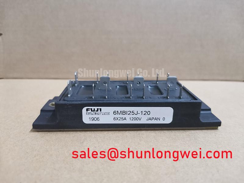

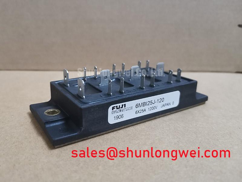



Content last revised on September 24, 2026
Preventing Spurious Faults: Galvanic Gate Drive Isolation for 6MBI25J-120
When a compact industrial inverter trips immediately after a module replacement, start at the gate drive connector and the isolation barrier rather than assuming the power module is the only fault location. With control power removed, compare the gate drive path, emitter reference path, connector seating, and cable routing against an unaffected phase or a known good board. A damaged isolation component, poor return path, or contaminated connector can create an unintended gate pulse that appears as a random inverter fault.
Design Consideration: galvanic gate drive isolation must be selected and validated for the actual common mode voltage movement in the finished inverter. Reinforced isolation claims and common mode transient immunity figures belong to the isolated driver or isolator documentation, not to the 6MBI25J-120 module unless expressly published for the module. Engineers should maintain clear separation between low voltage control traces and switching nodes, then verify gate to emitter waveforms during real switching tests.
Do not transfer thyristor concepts such as IGT, VGT, or force fired pulse trains to this IGBT module. An IGBT gate is voltage controlled, so repair work should focus on the driver supply condition, gate reference integrity, commanded pulse shape, and whether the device is being held securely off when its complementary switch is active. Fuji Electric provides family level context for power switching products in its Brake Chopper IGBT Modules material, but the original machine documentation remains the controlling source for this module’s drive conditions.
Field Diagnostics & Commissioning: SCSOA Overcurrent Protection in 6MBI25J-120 Topologies
During commissioning, confirm that the control board can detect abnormal current and remove the gate command before the power stage is subjected to sustained fault energy. Short circuit protection timing, desaturation thresholds, soft turn off behavior, and any staged shutdown sequence are system protection functions. They cannot be inferred from the stated 1200 V and 25 A ratings alone.
Engineering Recommendation: capture phase current, DC link voltage, and gate command signals with correctly rated test equipment while reproducing the operating condition that caused the trip. A current excursion may be associated with a load fault, incorrect phase angle control, gate command overlap, unstable line ripple handling, a damaged current sensor, or an unsuitable protection response. Compare the trace with the known good signal path before changing components.
RC snubbers can influence switching transients, but their values must be established from measured waveforms, switching frequency, bus structure, and the protective voltage boundary of the complete system. The same applies to semiconductor fuses. Fuse I²t coordination is a system level assessment involving the available fault energy, conductor arrangement, contactor behavior, and protection sequence. It should not be represented as an inherent fuse requirement of this specific module.
For equipment using related Fuji Electric power stages, 2MBI150UC-120 can be reviewed as a separate topology component. Its presence in a system does not establish interchangeability, because circuit function, terminal layout, voltage class, current duty, and gate drive arrangement must all be checked.
Benchtop Waveform Tuning: Managing Stress and Parameter Mismatch on 6MBI25J-120
Before applying full bus power, inspect the busbar stack, module terminal contact surfaces, gate lead routing, and heatsink interface. A loosely seated terminal or an uneven clamping surface can make waveform results misleading and can obscure the original cause of a drive failure. For multi device arrangements, use matching physical gate loop routing and compare each channel’s measured turn on and turn off behavior under controlled conditions.
Design Consideration: positive temperature behavior of IGBT conduction voltage can support static current sharing in suitable parallel arrangements, yet dynamic sharing also depends on the driver, gate path symmetry, switching timing, stray inductance, and device characteristics. It must be proven by measurement in the finished assembly. The official data stated here does not provide VCE(sat), gate charge, reverse recovery behavior, or a softness factor for the associated freewheel path, so none should be assumed during tuning.
Where a repair engineer is assessing a different current class within the same equipment family, 6MBI300U-120 is a separate module that requires an independent mechanical, electrical, thermal, and control compatibility review. It should not be installed as a direct substitute based on product naming alone.
⚠️ Field Alert: Disconnect and verify discharge of stored DC link energy before touching module terminals, gate cables, or measurement probes.
6MBI25J-120 Thermal Electrical Optimization: Active Miller Clamp Integration
Cross conduction investigation starts with simultaneous gate to emitter measurements on the complementary switching positions. A gate that rises while its device should remain off may indicate capacitive coupling through the Miller path, an excessive shared return inductance, poor driver reference control, or a probe arrangement that is distorting the observation. Verify against the original driver schematic and a known good channel where possible.
Engineering Recommendation: an active Miller clamp can be evaluated where the selected driver supports it and testing shows that switching node movement is coupling into an off state gate. Negative gate bias is also a driver system choice, not an official rating stated for the 6MBI25J-120. Its permitted range, clamp operation, driver supply sequencing, and protection interaction must be confirmed using the original module and driver documentation.
Keep the commutation loop compact and minimize parasitic inductance to suppress turn off overshoot. The final layout, snubber network, driver impedance, and protection thresholds are determined by measured peak voltage, current, temperature, and switching behavior in the actual inverter or high speed CNC spindle drive. For wider context on power semiconductor use cases and diagnostic priorities, see Industrial Applications. Fuji Electric also describes relevant module families through its RC IGBT Modules reference.