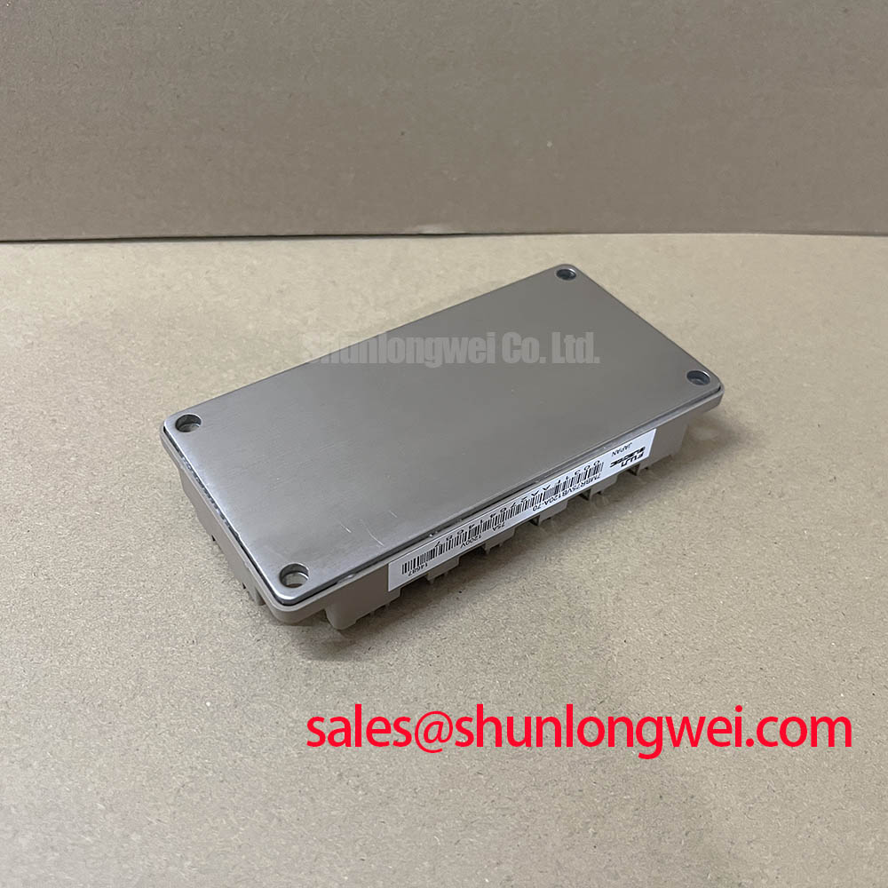



Content last revised on September 28, 2026
7MBR75VB120A-70 Operational Boundaries: Evaluating Thermal Time Constants and Peak Junction Limits
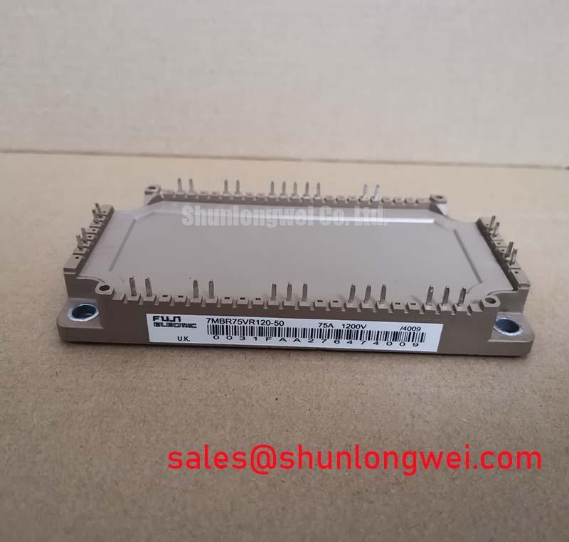
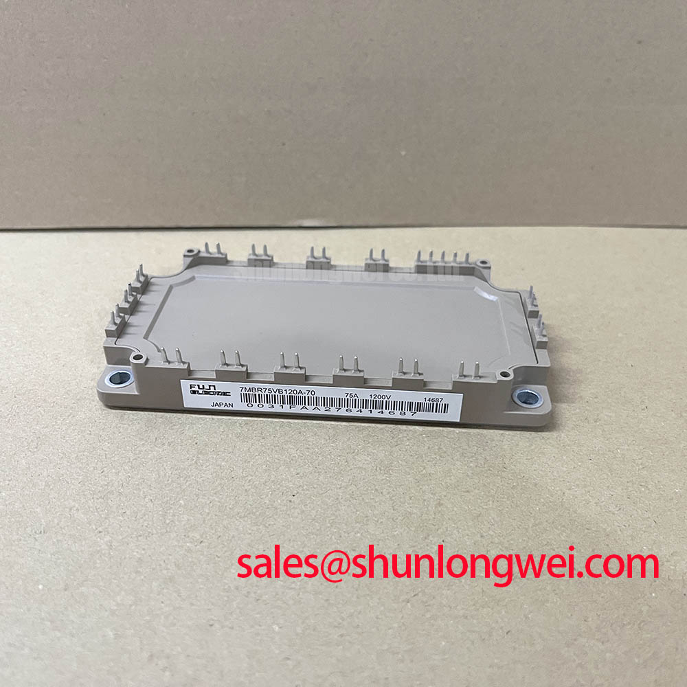
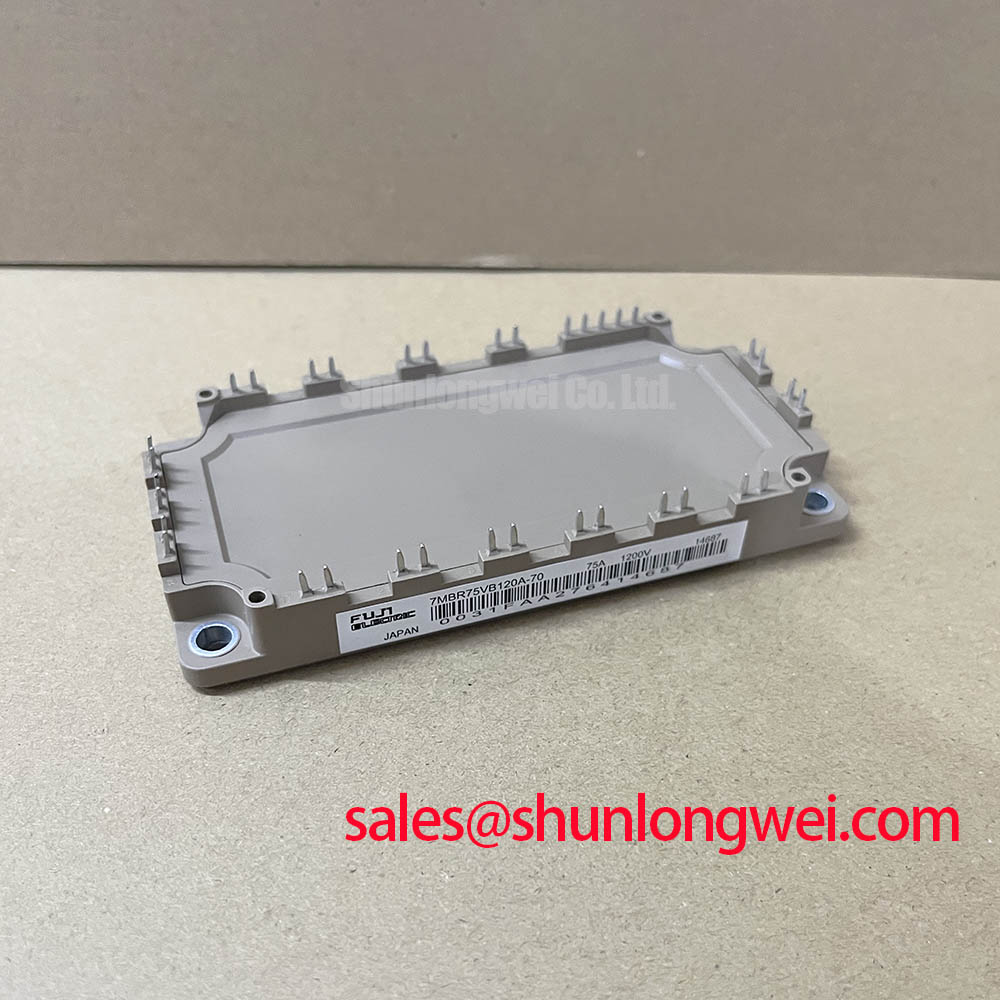
Begin a replacement inspection by isolating the drive, checking the module terminals for unintended low impedance, and verifying the nameplate electrical limits before applying DC link voltage to the 7MBR75VB120A-70. The Fuji Electric PIM module is specified for a 1200 V collector emitter voltage and a 75 A collector current at Tc = 80°C. These values define the starting point for compatibility review, not an automatic guarantee of performance in every inverter topology.
The published thermal and conduction data should be read together when assessing a heavy duty variable frequency AC motor drive. Fuji Electric specifies a typical Vce(sat) of 2.35 V at 75 A, a typical Vce(sat) of 2.50 V at 35 A, and a typical forward voltage of 1.5 V at 75 A. The specified power dissipation is 385 W per device. These are official specification values, while the actual junction temperature during a drive cycle depends on switching frequency, current waveform, case temperature, cooling path, duty cycle, and transient thermal impedance.
For pulsed overload analysis, engineers should use the manufacturer’s transient thermal impedance data for the applicable pulse duration and operating condition. A multi RC thermal model can then translate device power pulses into a calculated junction temperature rise. This is an Engineering Calculation, not an additional Fuji Electric rating. The calculated result should be checked against the module’s specified junction temperature limits and validated with thermal measurements under the real acceleration, regenerative braking, and motor-load profile.
In a repair evaluation, inspect the heatsink contact area, mounting flatness, thermal interface condition, and airflow path before attributing excessive temperature to the semiconductor itself. A drive that passes a static resistance check can still exhibit thermal stress caused by uneven clamping, blocked airflow, or a damaged gate-drive circuit. When the module is used in a high-power motor inverter, the system integrator should also verify the DC bus voltage, current crest factor, braking duty, and semiconductor switching losses against the complete thermal design.
The 1600 V repetitive peak reverse voltage and 75 A average output current are official specification values for the module’s rectifier section. They should not be treated as permission to operate beyond the inverter’s validated commutation and transient conditions. For neutral technical background during field evaluation, engineers may consult The Ultimate IGBT Knowledge Base.
Benchtop Waveform Tuning: Mitigating Hard Switching Transients on 7MBR75VB120A-70
Waveform verification should begin with a known safe test condition and an isolated measurement setup. Observe gate voltage, collector emitter voltage, phase current, and DC link behavior with probes and bandwidth suitable for the switching event. Excessive ringing may indicate a parasitic inductance problem, gate-loop impedance mismatch, unsuitable damping, or an interaction between the driver and the module. The corrective action should be selected only after comparing the measured waveform with the intended switching sequence.
The gate-drive loop should be kept compact, with the power commutation path separated from sensitive control wiring. If the module provides an auxiliary emitter or driver return connection, the system designer should confirm its terminal function from the original Fuji Electric documentation and route it independently from the high-current emitter path where the circuit requires a clean reference. This arrangement can help the driver sense the intended emitter potential rather than a voltage disturbed by load-current inductance.
Short-circuit protection requires special care. The supplied product information does not establish a verified short-circuit withstand time, type I or type II detection interval, or two-stage soft turn-off profile for this exact module. Those functions must therefore be confirmed from the applicable manufacturer documentation and tested at the intended DC link voltage, gate resistance, temperature, and current condition. A protection circuit that reacts quickly in a low-energy bench test may behave differently during a real inverter fault.
High-speed fuse coordination is also system dependent. The fuse clearing characteristic, semiconductor surge capability, wiring inductance, and available fault energy should be evaluated together rather than judged from fuse current alone. During regenerative braking, the chopper and braking resistor must absorb the energy permitted by the complete drive design. The module’s voltage and current ratings do not, by themselves, define the braking resistor rating or the safe energy duty.
💡 Pro Tip: Minimize the gate and commutation loop area, then confirm turn-off voltage margin with a properly referenced oscilloscope during double-pulse or equivalent switching tests.
7MBR75VB120A-70 Thermal-Electrical Optimization: Practical Reliability Assessment
FIT rate, single-event burnout probability, terrestrial neutron sensitivity, and altitude derating require a qualified reliability source for the exact device, application profile, and environment. No such field reliability dataset is established by the supplied product parameters, so a numerical FIT value, operating-life claim, or SEB probability should not be assigned to this module. At elevations above 2000 m, the system designer should review insulation coordination, cooling performance, creepage, clearance, and atmospheric effects using the applicable equipment standard and verified device documentation.
For a heavy duty variable frequency AC motor drive, DC bus headroom should be evaluated against measured switching overshoot, regenerative events, motor cable reflections, and abnormal load interruption. The design principle is to preserve sufficient voltage margin under the complete transient envelope; the final margin is determined by system testing and the applicable safety requirements. A single nominal bus-voltage calculation is not enough when long motor cables, braking choppers, or rapid load changes are present.
During troubleshooting, compare the suspect phase leg with a known-good phase leg under the same operating state. Check gate timing, collector emitter voltage, current balance, driver supply stability, isolation behavior, and temperature rise. A difference between phases may indicate a control, layout, connection, or semiconductor issue, so the measured evidence should be reviewed before replacing the module. Industrial optocouplers and digital isolators should be selected and tested for the required common-mode transient immunity within the complete gate-drive circuit; the module itself does not independently establish system EMC compliance.
For a neutral comparison point during sourcing review, 6MBI100S-140 may be evaluated as a separate Fuji Electric module according to its own published electrical, mechanical, and application data. It should not be treated as a direct replacement without confirming topology, terminal arrangement, gate-drive requirements, thermal interface, and protection coordination.
Transient Dynamics and Electrical Design: Thermal Paste Degradation Prevention
After removing a failed module, document the original mounting pattern and inspect the heatsink for burrs, contamination, local high spots, and signs of uneven contact. Clean both mating surfaces with a process approved for the equipment. The thermal interface material should form a continuous, controlled layer without visible voids, but the appropriate material, application thickness, and allowable surface condition must come from the module documentation and the equipment manufacturer’s assembly procedure.
Baseplate curvature and mounting sequence can influence thermal contact. Tightening should follow the specified cross pattern and torque procedure, using calibrated tooling and the correct hardware. Do not infer a model-specific torque value from a generic fastener table. Excessive force can distort the assembly or stress the module, while insufficient force can increase thermal resistance and permit movement during vibration or thermal cycling.
After installation, verify that power terminals, control terminals, and insulating barriers are correctly positioned. Check for unintended contact between busbars and the heatsink, confirm that the gate wiring is not routed beside high-current commutation conductors unnecessarily, and inspect the interface after the first controlled thermal test. The system integrator should establish acceptance criteria from the original equipment documentation, measured case temperature, and the applicable electrical safety requirements.
In the front-end topology, a separate rectifier or complementary power stage may be reviewed alongside the inverter leg. The 6MBI450U-120A-05 is presented as a separate product for such system-level evaluation, not as a prescribed companion or automatic substitute. Fuji Electric’s Power Semiconductors Portal provides manufacturer-level reference context for reviewing power module documentation.