


Content last revised on September 21, 2026
6MBP300VEA060-58 Circuit Protection & Reliability: Calibrating Junction-to-Case Thermal Network Simulation
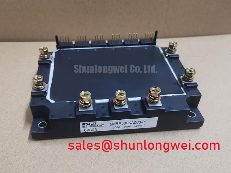
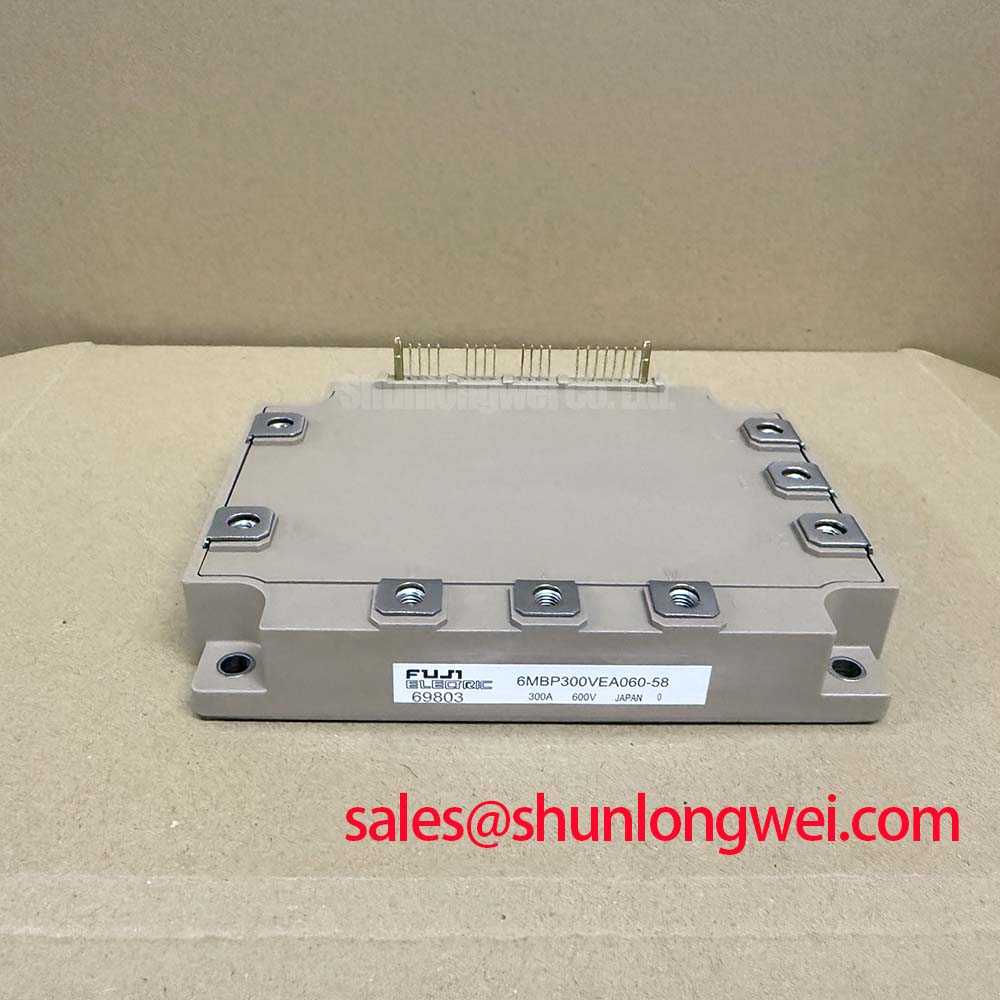
Before reconnecting a removed power stage, verify the nameplate against the inverter documentation and inspect the 6MBP300VEA060-58 terminal area, baseplate contact face, and control connector for damage that could compromise a repeat repair. This Fuji Electric IPM module is rated at VCES = 600 V and IC = 300 A at TC = 80°C, which are Official Datasheet Specifications and define the electrical boundary to preserve during evaluation.
The module includes overtemperature protection with a 125°C Tj trip level. This Official Datasheet Specification can support a system alarm or protective response, but it does not replace verification of the heatsink path, airflow, coolant condition, driver response, and load profile. In a pulsed industrial inverter welder or medium frequency induction heating supply, a short high-current event can raise junction temperature faster than the external heatsink temperature indicates.
For a junction-to-case thermal assessment, engineers commonly use the manufacturer-provided transient thermal impedance information where available and represent the thermal path with a multi-RC network. The calculation should combine measured or estimated semiconductor loss over the actual pulse profile with the transient thermal response, then compare the resulting peak junction temperature with the module's applicable operating limit from the original documentation. This is an Engineering Calculation, not a separate factory rating for the assembled power supply.
A recurring field issue is an apparently healthy heatsink combined with repeated thermal alarms. Possible contributors include incomplete thermal-interface contact, uneven mounting pressure, blocked airflow, unsuitable switching conditions, or increased output loading. Record control supply stability, alarm behavior, heatsink temperature, and switching waveforms before assigning a single cause. For device-level operating principles and structured diagnostic context, consult The Ultimate IGBT Knowledge Base.
Pro Tip: De-energize the DC link and confirm stored energy has been discharged before handling control or power connections.
6MBP300VEA060-58 Thermal-Electrical Optimization: Multi-Module Parallel Current Sharing Practical Tuning
When a power stage uses parallel semiconductor paths, static and dynamic current sharing must be evaluated separately. Under steady conditions, IGBT conduction behavior can support balancing through its positive temperature coefficient in the relevant operating region, but that characteristic alone cannot guarantee equal current distribution in a complete inverter. Busbar resistance, connection symmetry, thermal gradients, gate-drive routing, and timing variation remain system-level influences.
Design Consideration: Arrange parallel power paths so their DC-link and output-current loops are geometrically comparable. A laminated or closely coupled busbar layout can reduce parasitic loop inductance, helping limit turn-off overshoot. The system engineer should validate peak collector-emitter voltage against the 600 V Official Datasheet Specification during representative double-pulse and loaded switching tests.
Dynamic balance depends heavily on the physical gate loop. Driver outputs with unequal routing impedance can cause one branch to switch first and accept disproportionate transient stress. Match gate-return paths as well as gate-forward paths, place the driver architecture close enough to maintain a controlled loop, and assess switching traces with appropriately rated differential voltage and current probes. These are Engineering Recommendations; final component values and switching settings must be established from the complete system test results.
High-speed semiconductor fuse coordination also belongs in the fault-isolation review. The fuse clearing characteristic and its I2t behavior should be checked against the converter fault energy and the device-level surge information provided in applicable source documentation. A fuse is not a substitute for fast driver protection, because a power semiconductor fault can develop before a line-side protection device clears.
For architecture comparison, the 6MBI15L-060 can be reviewed as a separate power-module option within a broader converter chain. Its suitability must be determined by circuit topology, current demand, package interface, protection strategy, and original equipment documentation rather than by part-number proximity.
Benchtop Waveform Tuning: Mitigating Stress with SCSOA Considerations for 6MBP300VEA060-58
Protection validation should begin with captured gate, collector-emitter, and load-current waveforms under controlled conditions. The 6MBP300VEA060-58 uses a 15 V ±10% control supply, an Official Datasheet Specification. Verify this supply at the module interface while the converter is switching, since a rail that appears correct at idle can behave differently when driver isolation, gate charging, and auxiliary loads are active.
Short-circuit protection must be designed around the applicable safe operating conditions specified for the module and the driver architecture. Detection based on desaturation, current sensing, or another validated method should act within the protection timing proven by the system test. The proposed requirement for a response below 10 microseconds is a system-level Design Consideration, not an established performance claim for this individual module. Engineers should confirm the actual protection chain from fault recognition through controlled gate discharge using captured waveforms.
A two-stage soft turn-off approach can reduce the risk that an abrupt interruption of fault current produces excessive inductive voltage. Its effectiveness depends on gate-drive behavior, DC-link layout, load inductance, suppression network performance, and the selected protective threshold. The correct transition rate is system-determined and should be verified against collector-emitter voltage and current measurements rather than assumed from a generic driver setting.
MOV networks and other clamping arrangements may be assessed as coordinated system protection elements where the application requires transient-energy handling. Their placement, energy capability, repetitive exposure, and interaction with the DC-link capacitor must be validated in the actual circuit. The module's 2,500 Vrms for 1 minute isolation voltage is an Official Datasheet Specification between the power terminals and mounting baseplate; it should not be interpreted as a complete equipment insulation or EMC compliance statement.
For a potential lower-current comparative review, engineers can examine the 6MBI100L-060. Any replacement assessment requires confirmation of pinout, control interface, protection functions, mechanical fit, thermal capacity, and converter operating conditions.
Assembly Integrity & Layout Architecture: Baseplate Contact and Screw-Mounting Guidance for 6MBP300VEA060-58
Start installation by cleaning the mating heatsink and module baseplate with a process suitable for the assembly material, then inspect both surfaces under angled light for contamination, scratches, and local damage. A thin, uniform thermal-interface layer should fill microscopic surface irregularities without creating an unnecessarily thick thermal barrier. This is a General Industry Design Consideration, not an Official Datasheet Specification for the 6MBP300VEA060-58.
Baseplate curvature and heatsink flatness affect contact pressure across the module footprint. Use a sequential mounting pattern that brings the module into contact progressively and avoids concentrating stress at one corner. The exact screw type, torque, washer arrangement, interface material, and tightening sequence must follow the original module documentation and the mechanical design of the equipment. Do not infer a torque value from another Fuji Electric package or from a visually similar module.
After mounting, inspect the thermal compound boundary for evidence of uneven squeeze-out or gaps, then verify that busbars and power cables do not impose mechanical load on the terminals. Keep high-current commutation paths compact and symmetric to reduce parasitic inductance during switching. Maintain the creepage and clearance distances required by the finished equipment's voltage, contamination, insulation system, enclosure, and governing safety standard. This is a Design Consideration requiring system-level compliance review.
Control isolation deserves the same attention as the power layout. Optical or digital isolation devices in the driver chain should be assessed for their common-mode transient behavior under real switching conditions, while return-current routing should avoid coupling high di/dt power noise into low-level control references. Signal anomalies may indicate coupling, grounding, supply integrity, or measurement setup issues; compare against a known-good signal path with an oscilloscope before replacing parts.
The 125°C Tj overtemperature trip level should be verified as part of the complete alarm path after assembly, including controller recognition and equipment shutdown behavior.