



Content last revised on September 10, 2026
Sharp LQ104V1DG62 Replacement Inspection
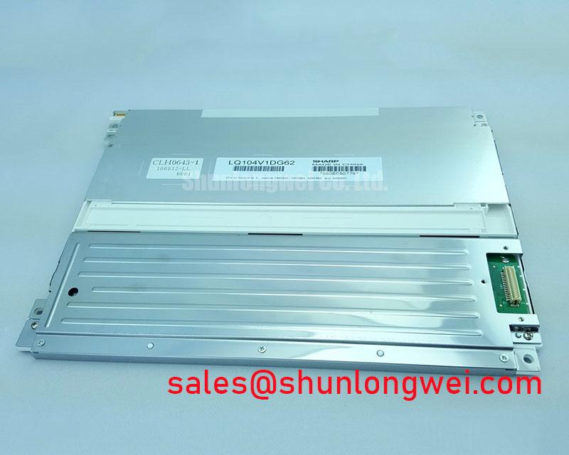
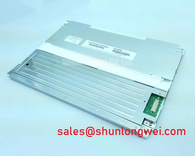
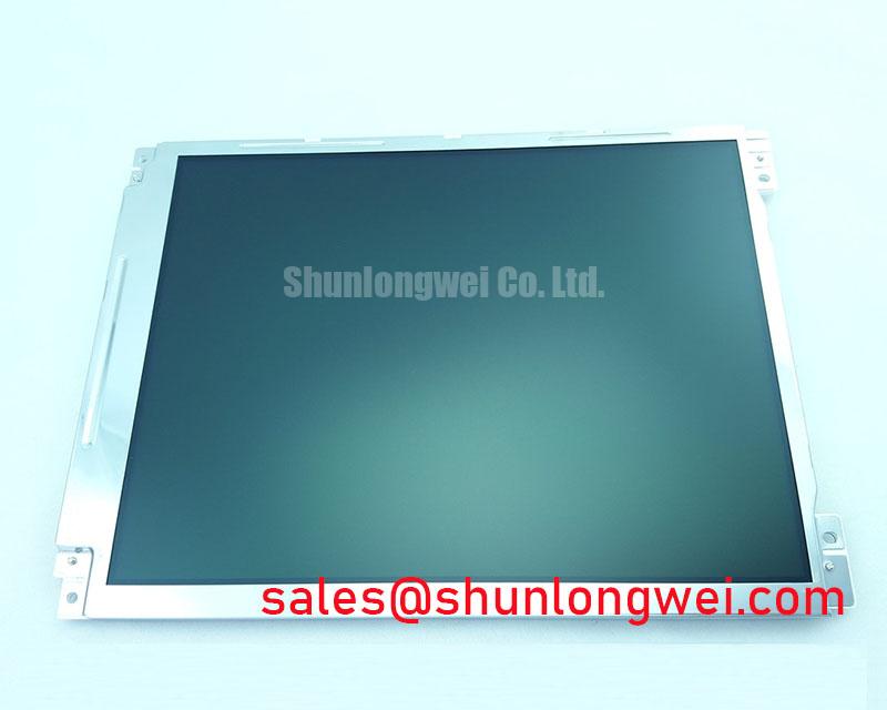
Begin a replacement inspection by comparing the installed panel label with Sharp LQ104V1DG62, then examine the glass edges, driver bond area, connector, and flexible cable before applying power. The available factory information identifies this unit as an Industrial Grade LCD/HMI Panel in a TFT LCD Display Module package, with Official Factory Spec Verified status. The supplied specification set does not confirm the panel resolution, active area, supply voltage, interface type, backlight technology, luminance, contrast ratio, touch function, or operating temperature range. Those items must be checked against the original panel documentation and the equipment service record before installation.
For overseas maintenance teams, this distinction matters. A display with the same diagonal size or connector appearance may still require different timing, power sequencing, backlight control, or mechanical support. Treat the LQ104V1DG62 as a model specific replacement candidate until the complete electrical and mechanical interface has been matched.
| Manufacturer | Sharp |
| Model | LQ104V1DG62 |
| Product category | Industrial Grade LCD/HMI Panel |
| Package | TFT LCD Display Module |
| Specification status | Official Factory Spec Verified |
Micro Twist Mechanical Stress Fracture Prevention on Glass Substrate Driver Bumps
When a control console shows a dark region, missing color, intermittent lines, or an image that changes as the bezel is touched, start with a non destructive bench inspection. Place the panel on a clean, level support and avoid lifting it by the glass or by the flexible circuit. Inspect the perimeter for chipped glass, lifted tape, folded flex material, and signs that the original bezel has pressed unevenly against the display. A small mechanical twist can alter contact at the bonded driver area, but a similar symptom can also come from the source board, cable seating, timing configuration, or backlight system.
Use a standardized primary color check after confirming that the host system supplies the correct voltage and startup sequence from the original documentation. Display red, green, and blue test fields separately, followed by white, black, and mid gray fields. Record whether the defect remains fixed at one glass location, follows the video source, or changes when the cable is repositioned without applying force to the panel. This three color check helps separate a color channel problem from a general illumination problem. It does not by itself prove a driver bond fracture.
A 45 degree flashlight inspection is useful when the screen appears black but faint image information may still be present. In a darkened service area, shine the light across the front surface rather than directly into it. If menu shapes or test patterns can be seen under external illumination, investigate the backlight supply and control path. If no image information is visible, verify the host output, panel power, enable signals, and cable continuity against a known good assembly. The factory information supplied for LQ104V1DG62 does not specify whether the backlight is CCFL or LED, so the replacement procedure must follow the original panel documentation rather than an assumed technology.
Interface timing also requires evidence from the source equipment. Do not assume that a similar connector means TTL or LVDS compatibility. Check the transmitter type, lane arrangement, pixel clock, color depth, power sequencing, and display enable behavior in the original system documents. During a fault investigation, an oscilloscope comparison with a known good signal path can reveal missing clock activity, unstable data transitions, or a timing relationship outside the host controller configuration. Clock jitter margin and data hold time are system interface characteristics; they are not confirmed factory parameters for this product entry.
For a same size or same resolution comparison, engineers may review LMS700KF01-001, but mechanical fit and electrical interchangeability must be verified independently. A cross reference is not an automatic substitute approval.
Shielded FFC and FPC Grounding across 360 Degree Connector Shells
Pixel jitter and horizontal noise bands should be investigated at the complete signal path rather than attributed to the LCD module immediately. With the equipment isolated, inspect the FFC or FPC for creases, contamination, incomplete insertion, damaged contacts, and strain at the connector exit. Confirm that the cable locking mechanism is fully engaged. If the display operates near variable frequency drives, servo amplifiers, or switching power equipment, route the video cable away from high current conductors where the cabinet design permits.
A shielded cable can only reduce coupled interference when its shield termination, connector shell, chassis bonding, and cabinet grounding arrangement are compatible. The panel listing does not provide a confirmed 360 degree shield termination requirement for LQ104V1DG62. The system integrator should therefore inspect the existing construction and preserve the original grounding method unless testing demonstrates a controlled improvement. Adding a random pigtail or bonding the shield at an unsuitable point can create a new common mode path.
If the original interface is documented as LVDS, the designer may use the documented differential impedance target as a layout and cable selection reference. A commonly used industry design consideration is a nominal 100 ohm differential path, but this is not an official electrical specification for the Sharp model unless stated in its applicable datasheet. Pair routing should remain consistent through the connector transition, and pair skew should be evaluated against the transmitter and receiver timing budget. The correct allowance depends on the host controller, cable construction, operating temperature, and signal rate.
Ferrite suppression is also system dependent. A common mode ferrite may reduce radiated susceptibility in one cabinet while producing unwanted edge distortion in another. Before fitting one, capture the differential clock and data waveforms at the display input and compare them with the source side. Check whether the disturbance is common to both conductors or appears as differential corruption. Verify the result during motor acceleration, regenerative braking, and other operating states that reproduce the fault. EMC performance belongs to the completed equipment; the display module itself must not be described as independently certified to a cabinet level EMC standard.
Power and communication checks should be performed together. An unstable panel supply can produce symptoms that resemble data noise, while a poor ground reference can disturb both the display logic and backlight control. Measure at the panel connector under operating load, confirm the return path, and compare startup behavior with the original unit. The required supply voltage and signal polarity should be taken from the original Sharp panel documentation or the equipment manufacturer’s interface records, not inferred from connector geometry.
⚠️ Field Alert: Disconnect equipment power and allow the system to discharge before inserting or removing the FFC or FPC, because live connector handling can expose signal and supply contacts to electrical stress.
Thermal Expansion Clearance across Heavy Industrial Metal Enclosure Cutouts
Before mounting the display in a metal enclosure, place the replacement unit beside the removed panel and compare the visible area, mounting hole pattern, connector exit direction, cable bend path, and bezel contact points. The supplied factory parameters do not include an outline drawing or dimensional tolerance for LQ104V1DG62. Do not machine a new cutout from the model number alone. Use the original mechanical drawing or measure the existing assembly with the panel unpowered and removed from the cabinet.
Heavy bezels can transfer cabinet distortion directly into the glass if the cutout is misaligned or the fasteners are tightened unevenly. A sound design consideration is to maintain even support around the approved mounting points while preventing the bezel from pressing on active viewing areas, glass edges, or flexible circuits. The exact clearance and fastening method must be determined from the panel drawing, enclosure material, gasket arrangement, and expected temperature range.
If M3 fasteners are used by the original mechanical design, the service engineer should follow the equipment maker’s torque specification and tighten in a cross pattern. The supplied official data does not confirm a torque limit for this model, so the commonly suggested values used for other display assemblies must not be presented as a Sharp factory requirement. After installation, check the panel on black, white, and gray fields. Localized brightness variation may be associated with mechanical pressure, mounting distortion, cable strain, or an optical assembly fault, and should be compared with the unmounted condition before any conclusion is made.
Outdoor bridge consoles and marine radar displays introduce additional compatibility questions. Direct sunlight, salt laden air, condensation, vibration, and enclosure heating should be evaluated at the equipment level. The current product data does not verify an anti glare coating, anti reflection treatment, optical contrast ratio at a defined illumination level, sealing rating, or salt spray qualification for LQ104V1DG62. If the panel is being evaluated for a harsh marine radar or navigation console, the integrator should confirm the viewing performance through the protective window, assess reflections at the operator position, and verify enclosure sealing separately.
Thermal management should focus on the assembled display and cabinet. Keep ventilation paths, cable clearances, and heat sources consistent with the original arrangement. Avoid placing a power converter or inverter directly against the rear of the panel unless the mechanical and thermal drawings permit it. The display listing does not provide a light guide plate construction, hot spot limit, thermal map, or maximum rear surface temperature. These characteristics must not be invented for procurement or retrofit decisions.
Touch functionality also requires confirmation. Although the product category includes industrial HMI use, the supplied factory data does not state that this exact unit includes resistive, capacitive, or any other touch technology. If the original console uses touch input, verify the touch controller, connector, calibration process, glove operation, and wet surface behavior as a complete system. A replacement LCD image panel should not be assumed to provide touch capability merely because it was installed in an HMI.
For additional enclosure and harsh environment evaluation practices, maintenance engineers can consult Industrial Display and HMI Solutions as a practical engineering reference. The final acceptance decision should remain tied to the original equipment requirements and documented test results.
Dual Channel CCFL High Voltage Inverter and Backlight Ignition Debugging
When the screen is faint, uneven, or briefly illuminated during startup, separate the image path from the backlight path before replacing the panel. Use the flashlight method described above to determine whether video data is present. Then inspect the original inverter or LED driver, its enable signal, current feedback, connectors, and protective shutdown behavior. The official information supplied for LQ104V1DG62 does not identify a CCFL backlight, LED backlight, inverter voltage, striking voltage, dimming method, service life, or MTBF value.
Do not apply a guessed high voltage to the panel. If the installed equipment uses a CCFL inverter, follow the inverter manufacturer’s service procedure and use suitably rated probes and insulation practices. A cold ignition event can involve hazardous voltage, and the correct operating values depend on the lamp arrangement, cable length, inverter topology, and protection circuit. If the original system uses an LED driver, confirm the required current regulation, enable logic, fault feedback, and dimming interface from the driver documentation. CCFL and LED assemblies are not interchangeable by visual inspection.
Acoustic buzz, repeated ignition attempts, or an illuminated strip that shuts down should be logged alongside supply voltage, enable state, driver fault output, and temperature. These observations help distinguish a driver protection response from a connector issue, lamp aging, thermal stress, or a panel level fault. Avoid treating one symptom as proof of a single failed part. Compare with a known good display assembly where possible, and preserve the original wiring arrangement during the test.
PWM dimming performance and brightness uniformity must be validated with the complete driver and host controller. The available specification does not verify a 1000 to 1 dimming range, a particular PWM frequency, or a luminance value for this Sharp module. Likewise, no authorized field life or half life data has been supplied for this product entry. Procurement and maintenance documents should therefore use the manufacturer’s applicable datasheet and equipment qualification records when defining brightness retention, operating temperature, or service expectations.
Before releasing a repaired console, run the panel through startup, shutdown, brightness changes, full color fields, gray scale transitions, and the operating conditions that previously produced the failure. Confirm that the image remains stable after the enclosure is secured, since cable pressure and chassis movement can alter the result. Record the verified interface, mounting drawing, backlight configuration, and host timing settings with the replaced Sharp LQ104V1DG62 so the next service intervention is based on documented compatibility rather than connector appearance.



