

Content last revised on September 13, 2026
LQ104V1LG81 Product Identity and Inspection
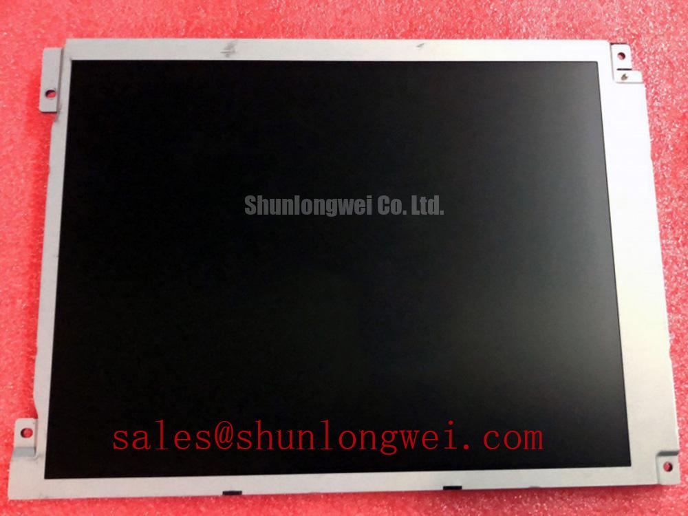
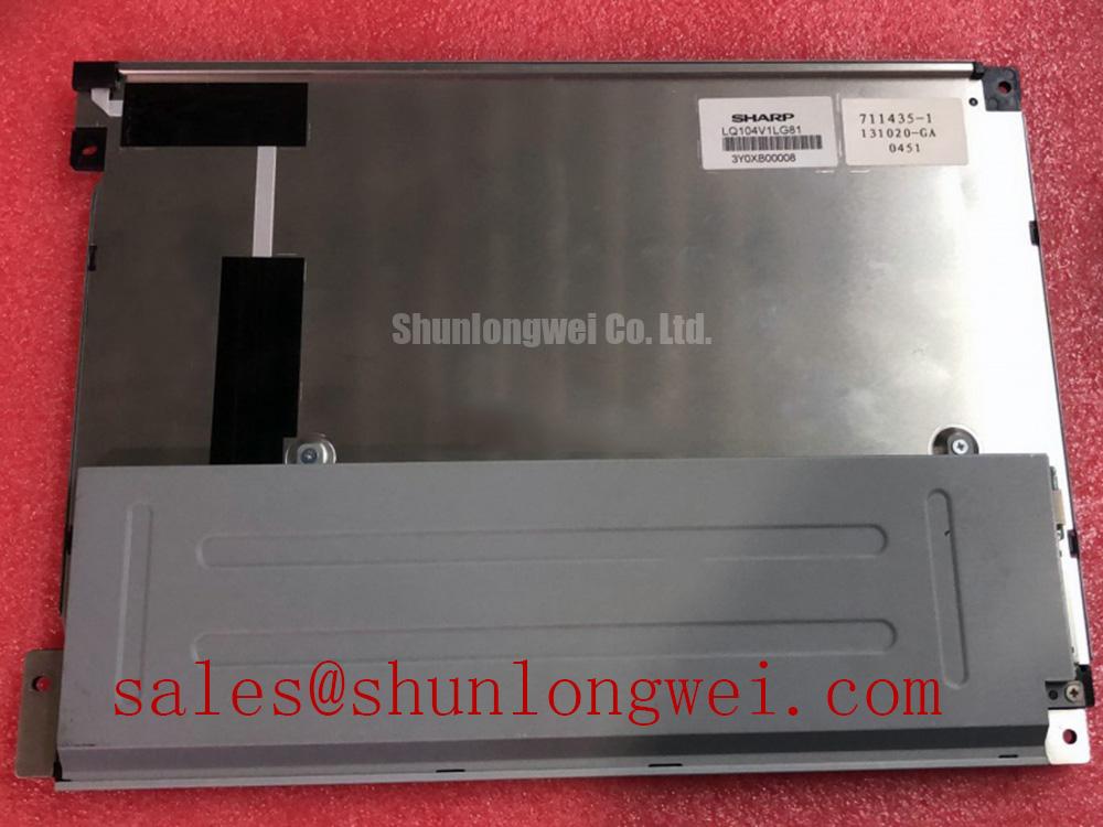
Before applying power, inspect the LQ104V1LG81 TFT LCD Display Module for cracked glass, damaged connector areas, bent contacts, contamination, and frame distortion, then compare the replacement unit with the removed Sharp panel and the original equipment documentation.
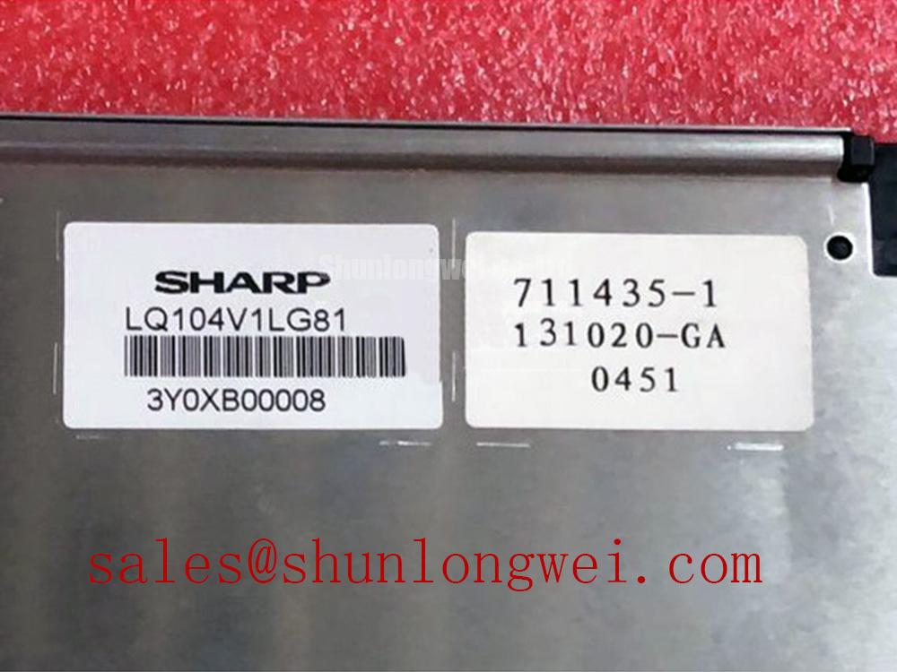
The LQ104V1LG81 is identified in the supplied factory specification context as a Sharp Industrial Grade LCD/HMI Panel. Its package description is TFT LCD Display Module, and its specification status is listed as Official Factory Spec Verified. These facts establish the product category and manufacturer identity, but they do not by themselves confirm interface type, supply voltage, backlight architecture, optical mode, resolution, viewing angle, or mechanical mounting dimensions.
That distinction matters during emergency repair. An LCD module can fit the opening of a control cabinet while still requiring a different cable assignment, timing configuration, backlight driver, mounting arrangement, or power sequence. The system integrator should verify every unlisted electrical and mechanical requirement against the original Sharp panel documentation and the equipment service manual before installation.
| Parameter | Information available for this product page |
|---|---|
| Model | LQ104V1LG81 |
| Manufacturer | Sharp |
| Product category | Industrial Grade LCD/HMI Panel |
| Package or housing description | TFT LCD Display Module |
| Specification status | Official Factory Spec Verified |
| Interface, resolution, supply, backlight, and dimensions | Verify from the original panel documentation before system integration |
Radiated Emissions Compliance Through Backplate Grounding and Cable Control
When this Sharp display is evaluated for a high-voltage substation protection terminal or SCADA dispatch console, begin with the cable path rather than the LCD glass. A dark image, intermittent pixel activity, or horizontal noise bands can arise from several conditions, including unstable supply rails, connector contact resistance, poor signal reference, cable routing near switching conductors, or a disturbance introduced by the host display controller. The visible symptom does not identify one cause on its own.
As a Design Consideration, the display cable should be routed with a controlled return path and kept away from high dv/dt and high di/dt conductors wherever the enclosure permits. If the equipment uses a shielded FFC, LVDS cable, or another high-speed display connection, the shield termination strategy must be checked against the controller, backplate, chassis, and protective earth arrangement. A 360-degree shield termination may be considered where the cable and connector system support it, but it must be validated against the actual enclosure topology. The LQ104V1LG81 factory information supplied here does not confirm a specific LVDS pinout or shield construction.
Backplate grounding should be treated as a system EMC design task, not as an inherent compliance claim for the LCD module. A multi-point grounding arrangement can reduce unwanted reference movement when it is implemented with a low-impedance chassis structure, but poor bonding can also create circulating currents or transfer drive noise into the signal reference. The correct arrangement depends on cable shield construction, controller grounding, cabinet bonding, and the site’s earthing design.
Common-mode ferrite components may be evaluated when conducted or radiated interference remains after cable routing and bonding have been checked. Their impedance behavior depends on cable geometry, operating frequency, current, and the selected component. Engineers should measure the known-good signal path with an oscilloscope and compare it with the suspect installation while monitoring the display supply, enable signals, clock activity, and data transitions. A ferrite should not be added as a substitute for correcting a loose connector, an incorrect cable assignment, or an unstable power source.
Cold-temperature operation requires additional caution. Liquid-crystal response can change as ambient temperature falls, and a moving image may show increased response lag or a change in gray-level transition behavior. The supplied product data does not provide a confirmed operating temperature range, gray-to-gray response specification, heater rating, or cold-start sequence for this model. If the host equipment includes a heater strip, the system designer should verify heater placement, control logic, warm-up behavior, condensation management, and the display manufacturer’s environmental limits through the original documentation.
CISPR Class A or Class B performance is determined by the completed equipment, its enclosure, cabling, grounding, power conversion, and operating state. The LQ104V1LG81 should therefore be evaluated as one part of the assembled system. The LCD module itself should not be described as independently certified to an EMC limit unless an applicable manufacturer document explicitly states that certification.
For broader enclosure, grounding, and harsh-environment test planning, engineers can consult Industrial Display & HMI Solutions as a practical reference point. It should supplement, not replace, the panel documentation and the equipment manufacturer’s compliance test plan.
Heat Spreader Placement Along Narrow Display Edges
Thermal inspection should start with the complete display assembly installed in its intended bezel. Measure the temperature distribution around the panel perimeter, controller board area, backlight region, nearby power conversion parts, and enclosure surfaces under the actual operating image and brightness settings. A local hot spot may be associated with the backlight driver, a restricted airflow path, a nearby heat source, or mechanical contact that transfers heat into one edge.
An aluminum heat spreader rail can be considered when the enclosure creates a localized temperature concentration along a narrow display edge. This is a Design Consideration, not a confirmed construction feature or factory requirement of the LQ104V1LG81. The spreader must be electrically isolated where necessary, mechanically supported without loading the glass, and positioned so it does not obstruct connectors, flex cables, vent paths, mounting points, or optical surfaces. The final material, thickness, contact area, and attachment method should be selected from measured heat flow and enclosure constraints.
Thermal interface placement deserves the same care as the spreader itself. A rigid clamp or uneven frame can apply stress to the display assembly, while an incomplete interface can leave the hottest region thermally disconnected. The interface should follow the equipment designer’s mechanical tolerances and approved material list. Do not press directly against the active viewing area or assume that a visually similar panel accepts the same frame pressure as the removed unit.
The supplied factory parameter set does not confirm an IPS, MVA, or other optical mode for this model. It also does not provide a verified contrast ratio, sunlight readability value, anti-glare coating specification, optical bonding status, light-guide construction, PMMA formulation, or L70/B50 backlight lifetime rating. Those values must not be inferred from the model number. If the panel is considered for direct-sunlight service, the integrator should verify contrast under the actual optical stack, cover glass, bezel, ambient illumination, and viewing direction.
Long-term backlight performance is affected by junction temperature, drive current, brightness control, airflow, enclosure temperature, and operating duty. A display module’s nominal category does not establish a guaranteed service life for the complete HMI. Where the original equipment uses a brightness controller or PWM input, the system engineer should confirm that the controller’s voltage levels, frequency behavior, duty response, and startup timing are compatible with the documented panel interface. No PWM frequency or duty-cycle linearity value is confirmed for the LQ104V1LG81 in the supplied data.
For a suspected thermal fault, compare a healthy display with the replacement under identical image content and brightness settings. Check the supply at the panel connector during startup and high-brightness operation, then inspect for voltage drop across connectors and cable contacts. If a heat map shows an unusual edge concentration, verify whether the source is the display, the backlight driver, the host board, or a neighboring converter before modifying the mechanical assembly.
Humidity Storage and Delamination Prevention
Storage inspection should include the glass perimeter, polarizer surface, connector region, frame edges, and any visible adhesive or sealing interfaces. Look for haze, bubbles, stains, edge lifting, trapped contamination, or changes that become more visible when the panel is viewed at an angle. These observations are useful screening evidence, but they do not establish a qualified humidity life result for the LQ104V1LG81.
The supplied factory information does not confirm a 60°C and 90% RH storage rating, an operating humidity limit, a perimeter epoxy specification, or an optical bonding process. Accordingly, those conditions must be treated as proposed system validation conditions rather than product guarantees. Before placing the panel in a sealed industrial display enclosure, the system integrator should obtain the applicable Sharp environmental specification and define the required preconditioning, power-off storage, condensation control, and recovery checks.
Moisture management is especially important where the display moves between a cold service area and a warmer, humid control room. Condensation can form on connectors, cable contacts, cover surfaces, and internal enclosure parts even when the LCD itself continues to appear intact. The enclosure design should provide a controlled transition procedure and should prevent direct moisture ingress from fans, vents, door seals, cable glands, and washdown exposure where relevant.
Cold conditions can also alter liquid-crystal response and create visible motion lag. If the HMI must display rapidly changing alarm text, trends, or protection status, the complete unit should be checked at the intended temperature range using representative graphics. The host controller, timing source, backlight driver, and display must be assessed together. A heater may be considered where the equipment environment demands it, but heater activation thresholds, warm-up sequencing, thermal isolation, and condensation prevention remain system-level design decisions.
Optical bonding, if required by the equipment, should be confirmed from the original panel documentation rather than assumed from the TFT designation. A bonded cover can reduce internal air gaps in some assemblies, while a non-bonded construction may have different service, sealing, and optical behavior. The replacement process should preserve the original bezel geometry and avoid introducing pressure points or trapped particles that become visible in bright fields.
When a unit has been stored under uncontrolled conditions, allow the assembly to reach a stable environment before electrical evaluation. Then inspect the panel at low brightness and normal brightness, display white, black, red, green, and blue fields, and check for changes after warm-up. If haze or edge separation progresses, document the location and compare it with the original unit before concluding that the LCD cell or the backlight is responsible.
Incoming Benchtop Inspection of Driver Bonding and Cable Interfaces
Incoming inspection should separate optical symptoms from electrical and mechanical faults. Begin with an external examination under neutral lighting, then connect the panel only through the approved harness and controller identified by the original equipment documentation. The LQ104V1LG81 factory context confirms the model and TFT LCD Display Module category, but it does not provide a pinout, connector keying definition, timing table, supply specification, or backlight drive requirement in the supplied data.
A three-field primary-color test is useful for finding nonuniform illumination, persistent pixel defects, color-channel abnormalities, and areas that respond differently from the surrounding image. Use full-screen red, green, and blue fields, followed by white and black where supported by the test controller. Record whether a defect remains fixed with the image, changes with brightness, or appears only during cable movement. This sequence does not prove a particular internal failure; it narrows the area requiring electrical and mechanical verification.
A 45-degree flashlight inspection can help distinguish a dark region caused by missing illumination from a line or pattern associated with the image path. View the panel with the backlight on and off if the equipment permits safe control, and compare the reflected and transmitted appearance without touching the glass. A dark shadow that changes with viewing angle may require optical and backlight investigation, while a sharply defined line that follows image content may require cable, controller, or bonded-driver checks. These are diagnostic directions, not fixed failure signatures.
Connector contact should be checked for seating, latch engagement, contamination, cable bend stress, and movement at the cable exit. Inspect the host-side socket as well as the panel-side connector. Use the equipment’s approved electrical test method and avoid probing fine-pitch contacts in a way that can bridge adjacent pins. If the image changes when the cable is disturbed, compare the result with a known-good harness and verify signal integrity with suitable instrumentation.
COG or TAB bonding areas should be examined visually for lifted edges, visible line defects, contamination, or localized changes after thermal exposure. The supplied information does not confirm the internal bonding technology or provide an ACF inspection acceptance standard for this model, so microscopic fracture dimensions, bond-force limits, and field failure rates must not be invented. If a bonded-driver issue is suspected, document the symptom, temperature, image field, cable state, and controller configuration before escalating the repair decision.
Do not interchange the LQ104V1LG81 with another display solely because the diagonal opening appears similar. During a replacement assessment, compare connector position, active-area geometry, mounting-hole pattern, cable direction, display timing, backlight control, and enclosure clearance. The linked LMS700KF01-001 may be reviewed as a separate same-class display option, but compatibility must be established from documented electrical and mechanical data rather than visual resemblance.
🔧 Field Alert: Disconnect equipment power and follow the original discharge procedure before inserting or removing the display cable, because live connector handling can expose signal and power contacts to unintended electrical stress.
After installation, verify the image at startup, during brightness changes, during cable flex observation, and under the intended enclosure temperature. Confirm that alarm text, trend graphics, protection indicators, and operator touch functions, where applicable to the complete HMI, remain stable throughout the test. Record the panel model, host controller, harness identification, mounting condition, and observed behavior in the maintenance report so a later replacement is based on evidence rather than an unverified visual match.