

Content last revised on October 14, 2026
Chassis M3 Fastener Torque Sizing for Optical Mura Control
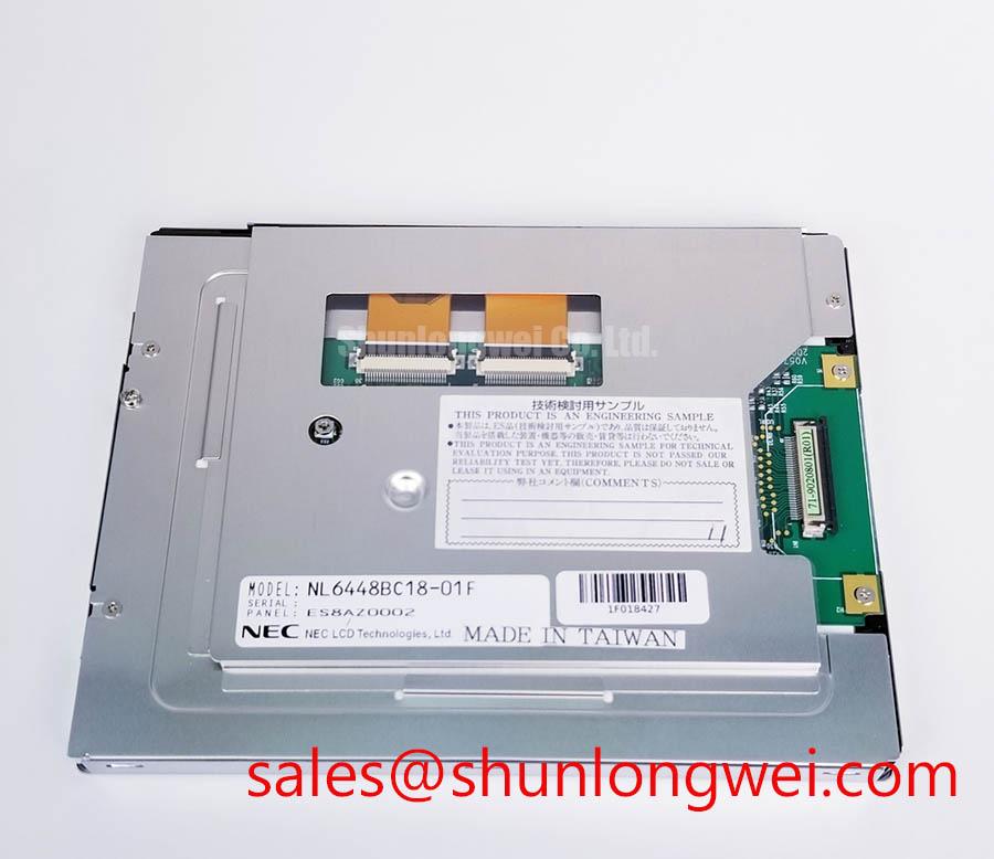
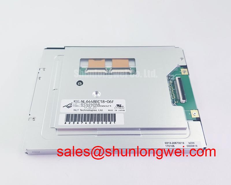
When a machine tool operator terminal reports a black screen, begin with the panel harness and power path: isolate the equipment, inspect the FFC or FPC seating, check for bent contacts, and compare the display supply rails with the original service documentation. The documented unit is the NEC NL6448BC18-06B, classified as an Industrial Grade LCD/HMI Panel with a TFT LCD active matrix color display module construction.
For a factory automation machine tool or HMI operator terminal, replacement work should treat the LCD module, display controller, backlight circuit, cable assembly, and chassis as one interface chain. The product record confirms the manufacturer as NEC; it does not establish unlisted supply voltage, interface pinout, optical dimensions, touch technology, or backlight drive requirements. The system integrator should verify those items against the original panel documentation before energizing the replacement.
Chassis M3 Fastener Torque Sizing for Optical Mura Control
Uneven bezel pressure can create dark areas, bright corners, or localized optical mura even when the display signal is correct. During removal, mark the original screw positions and release the frame evenly rather than levering against the glass edge. Inspect the chassis opening for burrs, twisted brackets, trapped cable insulation, and foreign particles that could press against the display perimeter.
Design Consideration: a cross-pattern M3 fastening range of 0.35 to 0.45 N·m is a general mechanical starting reference for a suitable display chassis, not an NEC factory specification for the NL6448BC18-06B. The actual limit must follow the panel drawing, bezel construction, screw engagement, gasket material, and enclosure stiffness. Tighten progressively around the perimeter while checking the screen at a uniform gray test image; a change in luminance near a fastener indicates that the mechanical stack-up needs correction rather than additional tightening.
Backlight control also affects visual quality. If the host system uses PWM dimming, the controller designer may evaluate a frequency range of 200 Hz to 1 kHz as a system-level design consideration, then verify flicker, acoustic behavior, camera-band interaction, and duty-cycle linearity on the completed assembly. The NL6448BC18-06B listing does not confirm a particular PWM input or backlight topology, so the original driver and connector documentation remains the controlling reference.
For a same-size or same-resolution service evaluation, engineers may also review NL6448AC18-08D as a separate display option. Mechanical, electrical, optical, and cable compatibility still require a direct system comparison before substitution.
Shielded FFC and FPC Grounding across Connector Shells
Pixel jitter and horizontal noise bands near a variable-frequency motor drive should be approached as a complete signal-integrity problem. First separate the display cable from motor and brake wiring, check whether the symptom changes with drive speed, and inspect the connector shell, shield termination, and chassis bonding points. A loose shield reference can leave the display signal operational while allowing common-mode noise to appear as moving bands or intermittent pixels.
Design Consideration: a 360-degree shield termination is commonly evaluated where the cable construction and connector shell support it. The shield path should be short, continuous, and bonded according to the enclosure grounding architecture. Do not attach a cable shield to an arbitrary signal pin or assume that connector metalwork is automatically bonded to protective earth. The correct connection depends on the host controller, cable assembly, and display interface design.
For high-EMI control cabinets, engineers may use 100 Ω ±10% differential-pair impedance and a skew target of no more than 50 ps as system-level layout references when the interface documentation calls for such control. These values are not confirmed electrical specifications for the NEC NL6448BC18-06B. The completed assembly should be checked with the applicable cable, connector, receiver, and timing requirements. If a ferrite component is considered, its impedance curve, current rating, placement, and effect on the differential pair should be evaluated rather than selected by appearance alone.
Power sequencing deserves equal attention. Disconnect the machine supply before removing the flat cable, then confirm that the controller and backlight rails have discharged according to the service procedure. ⚠️ Field Alert: Never insert or remove the display cable while the host controller is powered, because contact bounce can expose signal and supply pins to an uncontrolled transient. A related display topology can be reviewed through LQ104S1DG61, while its interface requirements must be treated independently from this NEC module.
Aluminum Heat Spreader and Thermal Interface Placement
Thermal inspection should focus on narrow edge zones, backlight driver locations, connector areas, and any point where the chassis presses against the rear of the display. A thermal camera can reveal gradients during a controlled run, but its reading should be interpreted with surface emissivity and reflective metal in mind. Do not add a rail or pad directly over a flexible circuit, exposed component, or optical area without checking clearance.
Design Consideration: an aluminum spreader rail can distribute heat along a narrow edge when the system enclosure has a defined thermal path. Its width, thickness, attachment method, insulation, and contact pressure must be determined from the chassis and panel drawings. Thermal interface material should be applied only where the mechanical stack permits it; excessive compression can introduce optical nonuniformity or stress at the display perimeter.
Cold operation changes the visual response of liquid-crystal displays. At sub-zero ambient conditions, gray-to-gray transitions may become visibly slower, producing trailing images or delayed level changes even when the video timing remains stable. If the machine requires cold start operation, the system designer should evaluate enclosure heating, startup sequencing, contrast behavior, and image response together. A heater strip is an optional system accessory, not a confirmed feature of the NL6448BC18-06B.
Backlight longevity should be assessed through the actual driver current, thermal path, duty cycle, enclosure temperature, and required luminance. L70 or B50 life figures must come from the applicable backlight documentation or test report; they should not be assigned to this model without a source. For industrial TFT background and optical terminology, engineers can consult The Ultimate Guide to Industrial TFT LCD Technology.
Humidity Storage Margins and Delamination Prevention
Before installing a stored panel, allow the complete assembly to reach a stable room condition inside its protective packaging, then inspect the perimeter, polarizer surface, connector region, and bezel for moisture marks or mechanical distortion. A display that powers on can still have optical or bonding damage, so inspect uniform gray and white images at controlled brightness rather than relying only on a logo screen.
Humidity exposure and thermal cycling can affect adhesives, seals, polarizer surfaces, and cable interfaces. Storage and transport limits should be taken from the applicable NEC documentation, while the enclosure designer controls condensation risk through sealing, drainage, pressure equalization, and thermal management. The stated industrial thermal range of a complete machine should not be treated as proof of an identical qualification for this individual display module.
Under cold conditions, increased liquid-crystal viscosity can lengthen gray-to-gray response and make motion artifacts more apparent. The practical test is to compare several gray transitions during cold startup and after thermal stabilization, while recording the controller timing and backlight state. Direct sunlight also changes the apparent contrast of an LCD. Optical contrast measurements, anti-glare behavior, and viewing-angle color shift should be checked in the finished bezel and cover-window assembly; a target such as greater than 500:1 at 50,000 lux is a system evaluation criterion, not a confirmed NL6448BC18-06B specification.
For industrial display reference material, the industrial TFT display solutions resource and NEC corporate resource provide broader manufacturer and industry context. They do not replace the model-specific documentation required for connector assignment, power sequencing, optical limits, or enclosure qualification.