



Content last revised on September 14, 2026
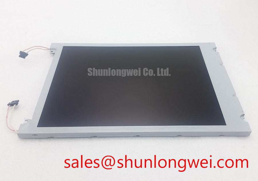
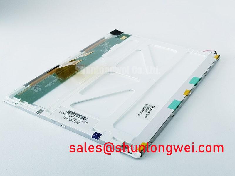
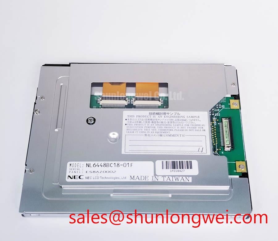
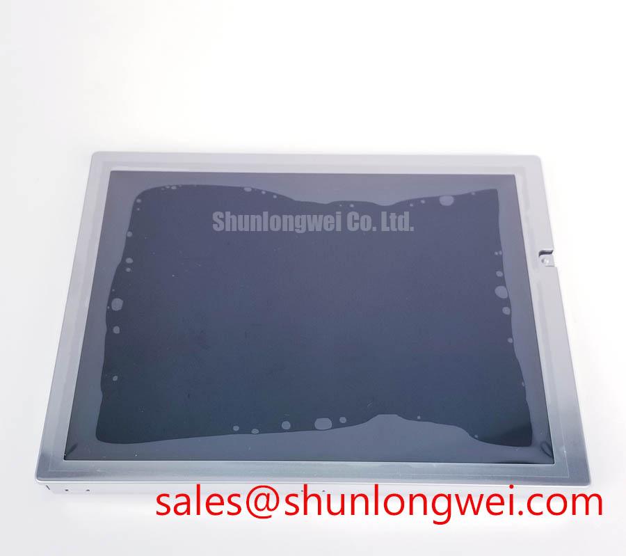
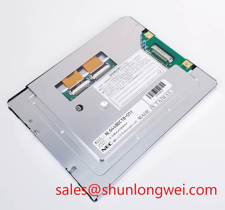
NEC NL6448BC18-01F TFT LCD Industrial HMI Panel
Begin a replacement inspection by recording the label on the installed panel, checking the enclosure for cracked glass or bezel distortion, and verifying the original system documentation before applying power to the NEC NL6448BC18-01F. This product is identified here as an Industrial Grade LCD/HMI Panel with a TFT-LCD Display Module construction. The available factory information confirms the manufacturer and product category, but does not establish undocumented interface, backlight, optical, or dimensional values.
For overseas maintenance teams, the correct replacement decision starts with identity and system compatibility rather than connector appearance alone. Compare the original panel marking, mounting envelope, connector orientation, cable routing, display timing, backlight arrangement, and controller requirements. The system integrator should verify the required supply voltage from the original panel documentation instead of assuming compatibility from the model number.
| Parameter | Available Factory Information | Engineering Handling |
|---|---|---|
| Model | NL6448BC18-01F | Match the complete suffix before procurement |
| Manufacturer | NEC | Confirm the marking against the installed display |
| Product category | Industrial Grade LCD/HMI Panel | Evaluate as a display module within the host equipment |
| Construction | TFT-LCD Display Module | Verify controller, cable, backlight, and mounting compatibility |
| Specification status | Identity and category information available | Use the original panel documentation for missing electrical details |
The panel may be evaluated for industrial operator stations, process monitoring interfaces, and control cabinets, including a hazardous-area enclosure where the complete assembly is appropriately certified. The LCD module itself must not be treated as independently certified for a Zone-2 installation, EMC compliance, ingress protection, or explosion protection. Those properties belong to the completed system and its approved enclosure, wiring, power supply, and installation method.
Industrial EMI Noise Immunity, Chassis Shielding Continuity and Common-Mode Ferrite Chokes
When a replacement display shows intermittent pixel jitter, horizontal noise bands, unstable grayscale, or a changing image near variable-frequency motor drives, start at the cable and chassis path. Power down the equipment, inspect both display connectors under magnification, and check whether the cable is fully seated without excessive bending at the connector body. A display fault should not be assigned to the LCD glass until the signal path, supply return, controller output, and enclosure bonding have been checked.
Shielding is a system-level design consideration rather than a confirmed specification of the NL6448BC18-01F. Where the host uses a shielded FFC or LVDS cable, the integrator should verify how the shield is terminated at the controller and panel sides. A continuous, low-impedance chassis reference can reduce susceptibility to common-mode interference, but the final grounding arrangement depends on the host architecture, isolation strategy, cable construction, and applicable safety requirements. Avoid creating an unplanned ground loop by bonding shields to arbitrary signal pins.
Common-mode ferrite chokes can be considered when conducted interference remains after cable routing, connector seating, and grounding have been verified. Their suitability must be confirmed against the differential signalling method and the display timing, because an unsuitable choke can increase edge distortion or reduce signal margin. Designers should observe the known-good signal path with an oscilloscope and compare the replacement assembly under the same operating conditions. The display module does not carry an independent claim of passing CISPR, EN 55011, or other complete-equipment EMC testing.
Backlight control also requires documentation review. If the host system uses PWM dimming, the controller supplier or original panel documentation must define the acceptable frequency and duty-cycle range. The suggested 200 Hz to 1 kHz investigation range is a design consideration for bench evaluation only, not an official rating of this NEC panel. Check for visible flicker, audible behaviour from the driver, brightness nonlinearity, and interaction with camera-based inspection systems before approving a replacement.
For a petrochemical operator station, inspect cable glands, bonding straps, cabinet partitions, and display-frame contact surfaces as part of the complete enclosure assessment. The display panel should be evaluated within the approved mechanical and electrical design rather than treated as the source of the enclosure’s hazardous-area compliance.
Single Vertical Hairline Defect and Sub-Pixel Column Driver Open-Circuit Localization
A single vertical line requires controlled comparison rather than an immediate assumption of backlight failure. Display a red field, then a green field and a blue field from the host controller, recording whether the line remains in the same physical position and whether its intensity changes with image content. Follow with a white field and a black field to separate a persistent image-column defect from an illumination or data-processing problem.
A 45-degree flashlight inspection is a useful design consideration during a dark-screen check. With the display unpowered or showing a black field as appropriate for the service procedure, use oblique light to look for surface damage, pressure marks, contamination, or a local shadow. This method can help distinguish an optical symptom from a signal-path symptom, but it cannot confirm a microscopic internal failure by itself. Do not press the active area, flex the glass, or manipulate the bonded edge while power is applied.
If the line changes with cable movement, first inspect connector retention, contact alignment, cable strain, and the controller output. If the line remains fixed while the cable and controller test normally, the service team may need to compare the panel with a known-good unit using the same source and timing. A COG or column-driver defect is a possible engineering interpretation only after external causes have been excluded; no field failure rate or internal fracture threshold is established by the available factory information.
Ambient light can make a low-contrast defect difficult to judge. Perform the comparison under controlled illumination and then repeat it under the actual operator-station lighting. Do not assign a contrast-ratio value, anti-glare performance, or sunlight readability rating to the NL6448BC18-01F unless those figures are confirmed in the applicable NEC documentation. A claimed value above 500:1 at 50,000 lux, for example, must not be presented as a product specification without a traceable source.
For procurement teams handling urgent repairs, document the defect location with a photograph, record the controller and cable part numbers, and preserve the original display settings. A same-size or same-resolution alternative such as NL10276BC16-06 should be evaluated only after connector, timing, mounting, backlight, and environmental compatibility have been checked. It is a compatibility candidate, not a prescriptive substitute for every installation.
Thermal Expansion Clearance Across Heavy Industrial Metal Enclosure Cutouts
Before installing the replacement into a metal operator-station cutout, compare the complete bezel envelope and the mounting-hole pattern with the removed unit. Check for burrs, paint buildup, warped sheet metal, gasket displacement, and uneven contact around the visible aperture. A panel that fits the opening can still experience local mechanical loading if the frame is twisted or if fasteners draw one corner down before the opposite side is aligned.
Mechanical clearance is a design consideration governed by the enclosure, gasket material, mounting bracket, temperature range, and panel construction. The available factory data does not confirm an outer bezel tolerance, allowable compression, or approved fastener torque for this model. Do not transfer a generic M3 torque value to the NEC display as an official limit. If the equipment documentation specifies a cross-pattern installation procedure, follow that documentation and verify that the frame remains flat as the fasteners are tightened.
Localized pressure can produce uneven luminance, dark-field mura, or a changing image appearance, but these symptoms require comparison under controlled conditions. Inspect the panel before installation, after fastening, and after the equipment reaches its normal operating temperature. If the appearance changes with enclosure temperature, examine mechanical stress, cable routing, airflow, and power-rail behaviour together. The evidence does not justify attributing the symptom to a particular internal light-guide material or structure.
For a sealed or purged hazardous-area operator station, the enclosure designer must separately verify gasket compression, viewing-window geometry, cable entry, heat dissipation, and certification requirements. Optical bonding, full lamination, anti-glare treatment, and moisture resistance must be confirmed from the exact panel documentation; they should not be inferred from the TFT-LCD category. If condensation or dust is observed, investigate the enclosure sealing and thermal cycle rather than claiming a panel-level ingress rating.
Timing compatibility also belongs to the host system. Confirm the controller’s pixel clock, data format, synchronisation method, signal polarity, startup state, and temperature-dependent timing margins against the original panel documentation. TTL or LVDS terminology alone does not prove interchangeability. When a screen shows white display, colour inversion, rolling content, or intermittent startup, capture the controller output and supply sequence with the known-good assembly for comparison.
⚠️ Field Alert: Disconnect power and allow the host supply to discharge before inserting or removing the display cable to reduce the risk of signal-pin transients and connector damage.
Backlight Drive, Power Sequencing and Long-Term Static HMI Operation
Backlight identification must be completed before the replacement is connected. The available factory record describes the unit as a TFT-LCD display module but does not confirm whether the installed version uses a particular LED or CCFL arrangement, its drive voltage, current, ignition requirement, or dimming method. The system integrator should verify the backlight type and driver requirements from the original NEC documentation and the host equipment schematic. Do not connect a driver based only on connector similarity.
High-voltage CCFL ignition and constant-current LED operation require different wiring, insulation, control, and fault-handling practices. Values such as 1,500 to 1,650 Vrms for cold ignition, 1,000:1 PWM dimming, or a 50,000-hour half-life must not be assigned to the NL6448BC18-01F without a model-specific source. They are investigation topics for a system design review, not confirmed characteristics of this product page.
Power sequencing deserves attention when the repaired HMI presents a white screen, delayed image, residual shadow, or an image that disappears during shutdown. Record the order and timing of controller power, panel supply, backlight enable, reset, and video signals on the known-good unit. Then compare the replacement while monitoring the supply rails for overshoot, collapse, ripple, and unexpected backfeed. The correct delay and discharge behaviour are determined by the panel documentation and host controller; they should not be replaced with a universal timing prescription.
Static process graphics can leave a persistent visual impression on any LCD system depending on panel technology, drive conditions, temperature, brightness, and operating pattern. For an HMI that displays fixed status bars or alarm icons for long periods, designers should review screen rotation, moderate brightness settings, periodic content movement, and the controller’s display-management functions. These are system-level recommendations, not a guaranteed burn-in prevention specification for this NEC model. Any required retention, lifetime, or half-life claim must come from an authoritative factory document or qualification report.
Differential-pair routing, impedance, skew, and common-mode behaviour should be checked against the original controller and cable design. Figures such as 100 ohms ±10 percent or 50 ps skew are not official specifications here and must not be inserted into a replacement approval merely because they are common design targets. Engineers should preserve the original topology where possible, minimise unnecessary cable length and discontinuities, and verify the final eye opening and timing margin under the actual motor-drive and enclosure conditions.
For broader repair and integration work, the The Ultimate Guide to Industrial TFT LCD Technology can serve as a reference for panel interfaces, selection checks, and common integration misconceptions. The final acceptance test for the NEC NL6448BC18-01F should use the host equipment’s original display profile, verified power sequence, mechanical fit, cable connection, image test pattern, and operating-environment checks.