Content last revised on September 25, 2026
NEC NL6448BC18-01B Product Overview and Verification Notes
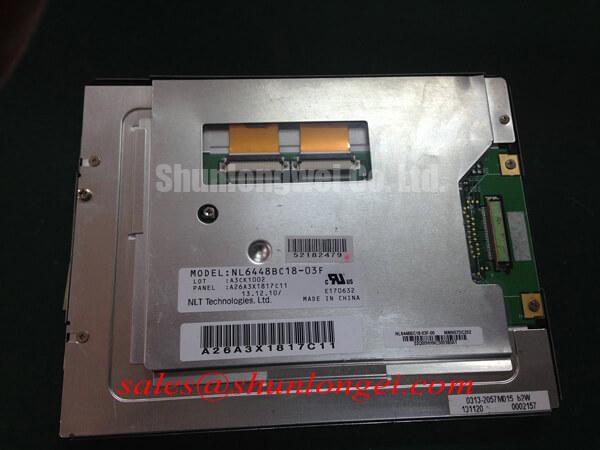
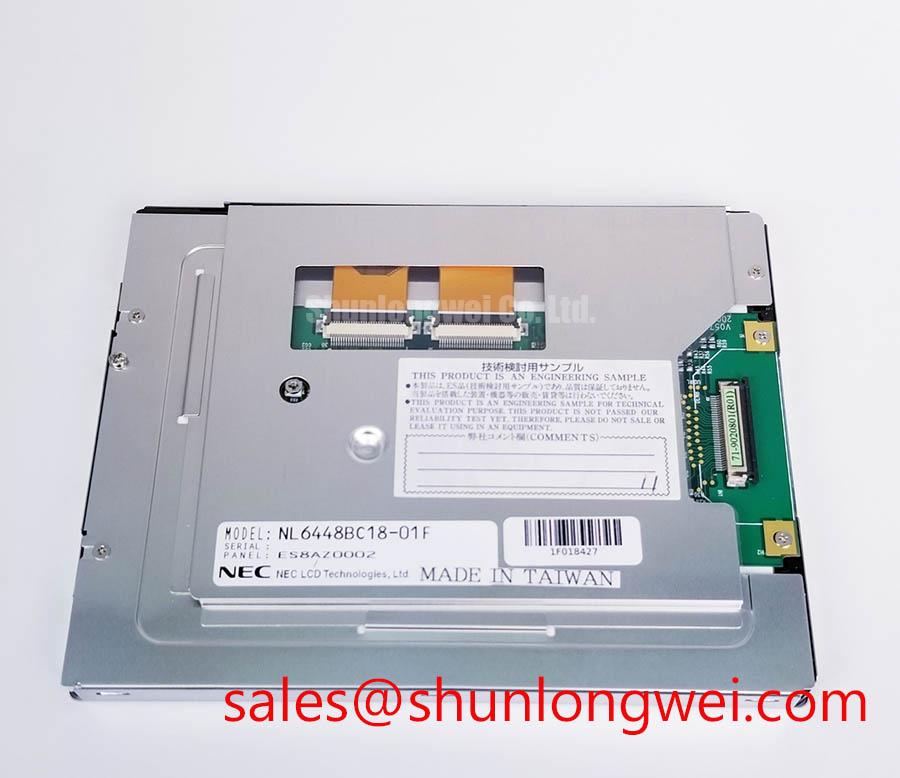
Before connecting the panel to a powered controller, inspect the NEC NL6448BC18-01B TFT-LCD display module for cracked glass, damaged flexible connections, bent connector contacts, and contamination around the display interface. Record the model marking and compare it with the original equipment documentation. The supplied factory record identifies this part as an Industrial Grade LCD/HMI Panel manufactured by NEC, with a TFT-LCD Display Module enclosure and an Official Factory Spec Verified status. For procurement and maintenance teams, the primary reference page is NL6448BC18-01B.
This page is intended for engineers evaluating a replacement display for control equipment, operator terminals, protection relays, and SCADA dispatch consoles. The factory information supplied for this product does not confirm the panel resolution, active area, supply voltage, interface pinout, backlight architecture, luminance, viewing angle, response time, operating temperature, or touch function. Those values should be checked against the original NEC documentation and the equipment manufacturer’s service documentation before installation.
| Item | Verified information |
|---|---|
| Model | NL6448BC18-01B |
| Manufacturer | NEC |
| Product category | Industrial Grade LCD/HMI Panel |
| Construction category | TFT-LCD Display Module |
| Specification status | Official Factory Spec Verified |
| Application reference | High-Voltage Substation Protection and SCADA Dispatch Console evaluation |
Full-Screen Primary Color AOI Screening: Stuck Sub-Pixels and Background Uniformity Audit
Run the first inspection with the display connected to a known-good controller and an approved power arrangement taken from the original panel documentation. Use full-screen red, green, blue, white, black, and neutral-gray images where the host system supports them. The purpose of this inspection is to identify visible pixel anomalies, broad luminance variation, intermittent image regions, and line-shaped defects while the panel is operating under controlled conditions.
Inspect each primary color at normal viewing distance, then move closer to the panel without pressing the glass. A stuck sub-pixel may remain visible on one or more solid-color fields, while a signal-path problem may appear as a larger line, column, block, or unstable region. These observations do not establish a single failure cause. Record the color field, screen location, persistence, and whether the defect changes after a controlled power cycle. Compare the result with the acceptance criteria used by the equipment owner rather than applying an unverified defect-count limit.
For background uniformity, use a white field at a stable brightness setting and examine the center, corners, and perimeter under consistent ambient lighting. A darkened region can be related to the backlight, optical layers, electrical drive, or the viewing setup. A 45-degree flashlight inspection can help separate a surface mark or local shadow from an illuminated image defect, but it is only a screening technique. When the panel is dark, illuminate the surface obliquely and observe whether the suspected area follows the glass surface or remains associated with the active image area.
When a line defect is present, compare it with the known-good signal path and inspect the panel connector for incomplete insertion or lateral movement. The supplied product record does not confirm whether this model uses LVDS, TTL, or another display interface, so the system integrator should verify the interface type and pin assignment from the original panel documentation. If the host uses a differential display link, trace impedance, pair routing, return-current control, and timing skew should be verified against the controller requirements. A nominal 100 ohm differential path is a host design consideration only when specified by the actual transmitter and receiver documentation; it is not a confirmed factory parameter for this panel.
For a high-voltage substation protection or SCADA console, record the image result before the panel is installed behind the bezel. This makes later troubleshooting more reliable because the engineer has a baseline for the display, cable, controller, and enclosure separately. If a replacement is being evaluated against another industrial panel, the NL10276BC16-06 may be reviewed as a separate same-category comparison candidate, subject to a full check of active area, resolution, interface, mounting, electrical requirements, and software compatibility.
Surface Anti-Glare and Anti-Reflective Evaluation for High Ambient Readability
Assess the installed display at the actual operator position, because surface reflections depend on the enclosure window, bezel depth, overhead lighting, sun exposure, and screen angle. Use a controlled white image and a dark image, then inspect the panel with the normal room lighting active. A reflective surface may reduce the visibility of dark text even when the panel itself is producing a valid image. A diffuse surface may reduce mirror-like reflections while changing the apparent sharpness of small characters.
The supplied factory data does not confirm an anti-glare treatment, anti-reflective coating, viewing angle, panel mode, or optical surface specification for the NL6448BC18-01B. Do not assign a TN, IPS, or MVA classification to this model without the applicable NEC documentation. Likewise, a symmetric viewing-angle figure such as 85 degrees in four directions must not be treated as an official value unless it appears in the model-specific specification sheet.
During incoming inspection, look for scratches, pressure marks, coating discontinuities, and contamination that becomes visible only under oblique light. Clean the surface using the method approved for the original equipment. Avoid aggressive rubbing and avoid applying liquid directly around the display edge or connector area. A surface appearance that seems acceptable under diffuse workshop light may become distracting inside a console with overhead task lighting, so the final review should include the enclosure and protective window when those parts affect readability.
Text readability should be assessed with the real user interface rather than a photographic test image alone. Check alarm messages, small status labels, trend graphs, and high-contrast symbols at the intended viewing distance. For a protection or dispatch console, compare the screen from the primary seated and standing positions and verify that critical status changes remain distinguishable without relying on a viewing-angle claim that has not been confirmed.
Touch operation requires a separate compatibility check. The supplied information identifies a TFT-LCD display module and does not confirm a resistive or capacitive touch layer. If the original assembly includes a touch overlay, verify its connector, controller, active area, mounting pressure, and glove or moisture performance from the complete equipment documentation. The LCD model alone should not be represented as having a specific touch sensitivity or water-handling capability.
Mitigating Gray-to-Gray Response Variation During Cold-Start Power-Up
Test cold-start behavior only within the environmental limits documented for the complete panel and host equipment. The provided factory record does not state an operating temperature range, storage range, gray-to-gray response time, liquid-crystal mode, perimeter seal construction, or thermal-cycle qualification for this model. A numerical cold-start claim, such as operation at minus 30 degrees Celsius or plus 85 degrees Celsius, would therefore require a model-specific source.
When a machine starts in a cold environment, allow the display to reach a stable state under the approved system conditions before judging text transitions or moving graphics. Record the initial image, the time at which the controller becomes active, and whether the apparent delay affects alarms, menus, or trend displays. A slow transition may involve the panel, the display controller, the backlight start sequence, the image source, or the application software. Use a known-good display and a controlled signal source to isolate these elements.
Backlight control also requires documentation-based verification. The supplied product information does not confirm whether the NL6448BC18-01B uses LED or CCFL backlighting, nor does it confirm a dimming method, driver voltage, ignition requirement, PWM frequency, duty-cycle behavior, open-circuit protection, or short-circuit protection. The system integrator should verify the required supply and backlight arrangement from the original panel documentation. Do not connect an assumed LED constant-current driver or an assumed CCFL inverter solely because another industrial display uses that architecture.
If the host uses PWM brightness control, designers should examine the relationship between the controller output, the display driver, and the operator’s visual environment. A PWM range such as 200 Hz to 1 kHz may be a system-level evaluation band for flicker and audible-noise testing, but it is not a confirmed specification of this NEC model. The engineer should verify image stability, camera interaction, audible behavior, and brightness linearity under the actual driver configuration.
Bench Tip: Disconnect power before inserting or removing the display cable, protect the panel and controller against ESD, and engage the connector evenly so the flexible cable remains straight and fully seated.
For thermal troubleshooting, inspect the bezel, cable routing, and enclosure airflow without assuming a proprietary internal seal or material construction. Look for mechanical stress that changes as the enclosure expands or contracts. If a fault appears only after heating or cooling, compare the panel with the cable disconnected and reconnected under safe service conditions, then use the known-good signal path to determine whether the change follows the panel or the system.
Backlight Drive, Dimming Behavior, and Flicker Suppression
Begin backlight diagnosis by separating image generation from illumination. With the controller active, check whether the screen produces a faint image when viewed under a suitable external light source. This observation can help determine whether the image path is active while the backlight path is not, but it does not identify the failed component by itself. Confirm the result with the equipment schematic, the original inverter or driver documentation, and controlled voltage measurements made by qualified personnel.
The supplied factory specification does not confirm a WLED constant-current circuit, CCFL inverter, ignition voltage, PWM dimming ratio, half-life, mean time between failures, or protection output. Values such as 1,500 to 1,650 Vrms for CCFL ignition, a 1,000 to 1 dimming ratio, or more than 50,000 hours of service life must not be assigned to the NL6448BC18-01B without a model-specific authoritative source. These figures may apply to other display assemblies and are not interchangeable product facts.
When the backlight does not start, inspect the host supply, enable signal, brightness command, connector seating, and driver status according to the original circuit documentation. An open-circuit or short-circuit indication may originate in the driver, cable, lamp or LED assembly, protection circuit, or controller configuration. Capture the fault indication and compare it with a known-good unit where available. Avoid repeated power cycling when the driver documentation identifies a protection latch or a required reset sequence.
Flicker evaluation should include low, medium, and high brightness settings, because a problem may appear only at one control point. Observe the display directly and, where relevant, with the camera used by the maintenance or monitoring system. Check for beat frequencies between the backlight control and the camera shutter, visible modulation during scrolling text, and audible noise from the driver or enclosure. The appropriate PWM strategy is determined by the confirmed panel and driver architecture, so the system designer should validate it with the actual assembly rather than importing a generic LED or CCFL setting.
Signal integrity remains part of the backlight investigation when the display is connected to a noisy industrial controller. Route high-current switching paths away from sensitive display wiring, preserve the intended return path, and verify the controller clock and data timing at the panel interface. If the interface is LVDS or TTL, confirm the exact electrical standard, voltage levels, pinout, termination, clock polarity, data mapping, jitter allowance, and hold-time requirements from the original documentation. A 100 ohm differential target or a 50 picosecond skew limit may be relevant to a particular host design, but neither is verified here as a specification of the NEC NL6448BC18-01B.
For equipment-level evaluation, the Industrial Display and HMI Solutions reference provides a broader framework for reviewing enclosure conditions, wiring, signal integrity, and environmental integration. The final compatibility decision for the NL6448BC18-01B should remain tied to the original panel documentation, the controller interface, the mechanical installation, and the measured behavior of the complete SCADA or protection-console assembly.