

Content last revised on October 18, 2026
Suppressing Ghosting and Crosstalk via Precision Multi-Level Bias Voltage Dividers
Ghosting and weak contrast in a passive matrix display often require attention to the bias network rather than the digital source alone. When evaluating a legacy drive assembly around the Sharp LM64C35 LCD panel, verify the required bias polarity, voltage range, and ripple limits against the original panel and controller documentation before making adjustments.
Measure the bias rail at the panel connector while the display is operating, then compare the reading during a full-screen text pattern and a high-density diagnostic pattern. A divider that is stable with a static image can still exhibit modulation when the line and frame drive activity changes. Keep the divider return path separate from noisy backlight switching currents, and inspect electrolytic capacitors, resistor drift, solder joints, and connector contamination before adjusting the contrast control.
Temperature compensation should be checked as a tracking function, not treated as a fixed contrast setting. A thermistor network can be used as a Design Consideration where the original display controller expects temperature-dependent bias correction. The correct coefficient, placement, and control range remain system-dependent. The purpose is to reduce contrast fade and excessive darkening across the actual enclosure temperature range without forcing the panel beyond its specified drive conditions.
If the original assembly uses a CCFL backlight, the cold-strike circuit requires separate safety evaluation. A 1200 V to 1600 Vrms ignition voltage may occur in some CCFL systems, so creepage, clearance, transformer insulation, and corona suppression must be assessed by the equipment designer. These values describe a possible host backlight circuit and are not confirmed electrical specifications for the LM64C35 panel itself. The Sharp Display Solutions Official Portal provides manufacturer-level display technology context for system evaluation.
Digital Parallel Bus Timing: FLM, LP and CP
When the image contains shifted characters, irregular line content, or a screen that remains white after power-up, check the parallel timing path and power sequence together. The signal names FLM, LP, and CP are commonly associated with frame synchronization, line transfer, and shift-clock functions in passive matrix display systems, but the exact bus width, pin assignment, and polarity must follow the original LM64C35 documentation and host controller design.
Use a known-good signal reference when checking the bus. Confirm that the frame pulse repeats consistently, that the line pulse remains aligned with the intended line data interval, and that the shift clock has clean transitions at the panel connector rather than only at the controller. Long unshielded traces, a loose flex connector, or a ground return shared with a switching backlight can create apparent timing faults. System designers should verify signal integrity with the panel installed in its final cable and bezel arrangement.
Power sequencing deserves equal attention. The controller supply, logic activity, bias generation, and backlight enable should be reviewed in the order defined by the original panel and equipment documentation. Incorrect sequencing can produce abnormal display drive conditions, including unwanted DC imbalance across the liquid crystal cells. The required delays and voltage thresholds should be validated during repeated power cycling rather than inferred from the model number.
| Evaluation item | LM64C35 | LM8V311 |
|---|---|---|
| Manufacturer | Sharp | Verify against original documentation |
| Product category | LCD panel | Display reference part |
| Panel technology | Verify against original documentation | Verify against original documentation |
| Form factor | Verify dimensions and mounting features | Verify mechanical and electrical compatibility |
The linked reference model should be treated as a comparison point, not an automatic substitute. Before approving any cross-reference, compare panel technology, resolution, active area, mounting features, connector orientation, pin assignment, bias requirements, backlight arrangement, and controller timing. A similar-looking panel can still require a different drive sequence or mechanical stack-up.
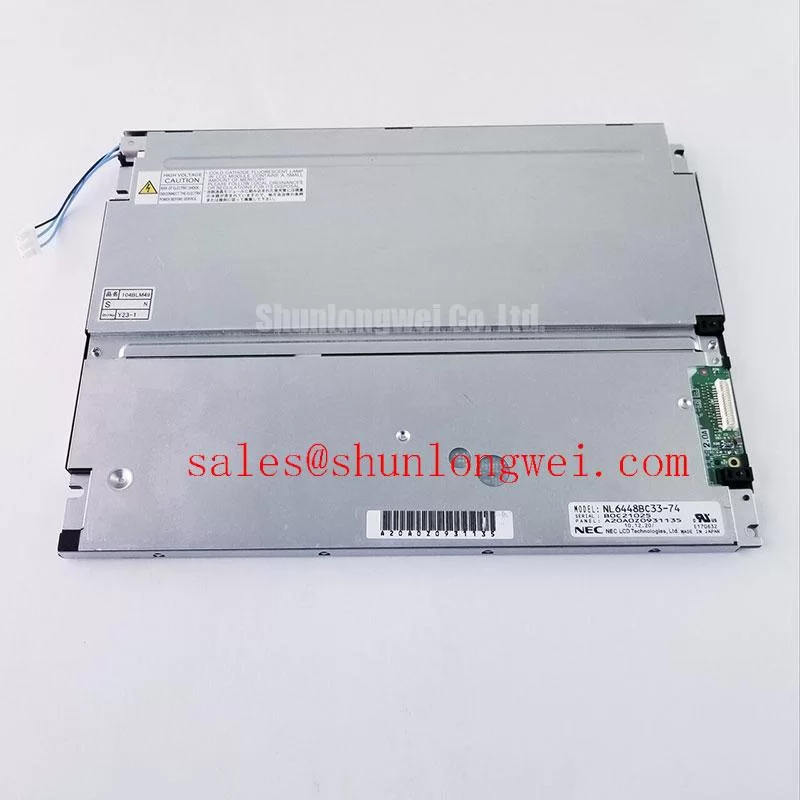
HV Lead Wire Creepage Insulation and Secondary Transformer Corona Discharge Screening
Backlight faults should be separated from liquid crystal drive faults before the panel is removed from the machine. Where the original assembly uses a CCFL inverter, an illustrative engineering review may include a 1200 V to 1600 Vrms cold-strike voltage, 300 V to 600 Vrms sustained operation, and tube-current regulation around 5.0 mA ± 0.5 mA. These are example host-inverter values, not confirmed LM64C35 product ratings or test settings; use the original lamp and inverter specifications for evaluation.
Inspect the high-voltage lead for insulation whitening, carbon tracking, pinched sections, and movement against the metal chassis. Transformer potting, lead exit geometry, and connector seating should be checked for corona activity under the actual enclosure conditions. The insulation system must be evaluated as a complete assembly because the panel, inverter, wiring, and grounded structure jointly determine the available clearance and leakage path.
Contrast complaints can also be influenced by optical and temperature conditions. Aged polarizer surfaces may show uneven darkening or reduced readability after prolonged heat exposure, while reflected ambient light can make a healthy image appear washed out. At sub-zero temperatures, liquid-crystal response becomes slower, so the display should be observed during the complete thermal transition within its specified operating range rather than judged from an immediate cold-start image. Designers evaluating long-term HMI service can use the industrial TFT LCD technology guide for broader display-system considerations, while keeping the LM64C35 assessment specific to its documented construction.
Investigating Intermittent Display Connections under Mechanical Vibration
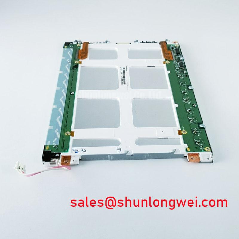
Missing rows or columns that change when the bezel is pressed should direct attention to the panel interconnections, bezel alignment, and panel compression. If the assembly uses an elastomeric connector, its conductive paths must remain correctly aligned with the contact pads across the full contact width; movement can interrupt selected lines while leaving the rest of the image active.
Where an elastomeric connector is present, use the original assembly or connector manufacturer's compression requirements. Excessive compression can distort the glass edge or elastomer, while insufficient compression can allow vibration-related separation. The correct loading depends on the frame geometry, gasket behavior, contact width, and mounting tolerance of the original equipment.
Clean accessible contact surfaces with a process approved for the panel materials, then check alignment marks, retaining features, and cable strain relief. Do not diagnose every intermittent column as a failed panel: compare the symptom while gently stabilizing the connector, inspect the controller-side flex termination, and monitor whether the fault follows mechanical movement. Any rework should preserve the original bend radius and avoid placing tensile force on the glass edge.
⚠️ Field Alert: Disconnect equipment power and allow stored energy to discharge before inserting or removing the panel connector, especially where a separate high-voltage backlight inverter is present.
For factory automation machine tools and HMI operator terminals, the LM64C35 should therefore be evaluated as a Sharp LCD panel within the complete display assembly. Final approval depends on matching the original connector, timing, bias generation, backlight circuit, mounting requirements, and environmental installation conditions.