Content last revised on November 5, 2026
Chassis M3 Fastener Torque Sizing to Eliminate Optical Mura Defects
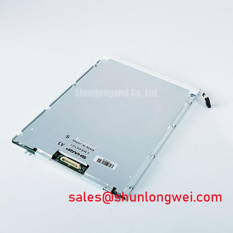
When a replacement display shows uneven dark areas after installation, inspect the bezel loading pattern before changing the display electronics. The LQ104V1DG81 is identified as a Sharp TFT-LCD Active Matrix Color Display Module in a standard industrial form factor, so mechanical fit, frame pressure, connector orientation, and viewing-window alignment should be checked against the original assembly.
Use the original panel outline and mounting-hole drawing to establish the chassis envelope. The bezel should support the module evenly without forcing the glass or pressing against the active image area. A cross-pattern tightening sequence can help distribute mechanical load, while the final fastener setting remains a Design Consideration determined by the chassis material, insert type, screw size, gasket compression, and panel support geometry. The supplied engineering reference identifies an M3 torque evaluation range of 0.35–0.45 N·m; this should be treated as an integration starting point rather than an LQ104V1DG81 factory rating.
Localized compression can alter the apparent uniformity of a liquid-crystal panel, particularly where a bezel edge, spacer, or cable fold transfers force into the display stack. Compare the panel with the bezel temporarily released and then with the final frame installed. A change between these two states points the investigation toward mechanical loading, optical spacing, or enclosure alignment rather than immediately toward a failed timing controller.
For high-EMI control cabinets, the interface board layout should preserve the transmitter and receiver topology used by the original equipment. Where a differential display link is present, the designer may evaluate controlled differential routing around 100 Ω ± 10% and a skew budget at or below 50 ps as general signal-integrity targets. These are Design Considerations, not confirmed electrical specifications for this Sharp module. Connector pinout, signal voltage, pixel format, and power sequencing must match the original panel documentation.
Engineers comparing physical replacement options can also review LQ121S1LG45 as a separate display option. It should be assessed independently for active area, resolution, interface, mounting geometry, and optical requirements rather than treated as an automatic substitute.
Edge-Lit LED Rail Thermal Dissipation and Light Guide Preservation
Thermal inspection should begin at the narrow display edges, where the backlight rail, enclosure wall, and nearby driver components can concentrate heat. The LQ104V1DG81 listing identifies the product as a TFT-LCD Active Matrix Color Display Module, but it does not establish a specific LED backlight architecture, optical material, brightness rating, or lifetime value in the supplied factory parameter set.
When the installed assembly uses an edge-lit LED arrangement, an aluminum spreader can be evaluated as part of the equipment-level thermal path. Its contact area, insulation, mounting pressure, and clearance from the display frame should be selected from the complete mechanical design. The purpose is to reduce localized hot spots without transferring stress into the panel or blocking the optical path.
Light-guide preservation depends on even support and stable thermal conditions. Avoid placing adhesive, cable clamps, or chassis ribs across unsupported optical regions. A visual comparison at cold start and after normal operating temperature can reveal whether brightness non-uniformity follows temperature, enclosure pressure, or backlight current. These observations help separate an optical assembly issue from a display-data or timing problem.
Backlight current must be controlled by the driver architecture used in the equipment. The system integrator should verify whether the original unit uses a constant-current LED driver, a separate backlight board, or another arrangement. Do not infer the required supply voltage, dimming method, connector assignment, or current limit from the LQ104V1DG81 model number alone.
For a related display-system evaluation, the complementary product TCG121XGLPCPNN-AN70 may be reviewed as a separate component. Its electrical role and compatibility must be confirmed within the actual backlight and display power topology.
Design Consideration: Keep the backlight heat path mechanically independent from the active display surface and validate brightness uniformity after the bezel reaches its normal operating temperature.
Contrast Stabilization and Liquid Crystal Temperature Tracking
Display contrast problems in an industrial HMI should be assessed across viewing direction, ambient illumination, temperature, and image content. The supplied product data classifies LQ104V1DG81 as a Sharp industrial LCD/HMI panel, but it does not confirm IPS, MVA, TN, anti-glare treatment, viewing-angle values, or contrast-ratio limits. These characteristics must be matched to the original display documentation and the equipment viewing position.
For a CNC operator panel or robot teach pendant, check the image from the actual standing and operating positions rather than judging the panel only from the optical axis. A grayscale test pattern can expose viewing-direction color shift, shadow detail loss, or gamma imbalance. Ambient factory lighting can also make a surface appear lower in contrast even when the video path is operating correctly.
The T-CON and source-driver system determine how incoming pixel data is translated into grayscale levels. When replacing the panel, the controller output format, bit order, frame timing, clock polarity, and power-up sequence must remain compatible. JEIDA and VESA-style mapping are not interchangeable assumptions; the integrator should compare the existing transmitter configuration with the required panel interface definition.
Temperature tracking should use the display’s specified operating range and the measured enclosure conditions. At low temperature, liquid-crystal response can change, causing visible gray-to-gray transitions to lengthen. At elevated temperature, contrast and black-level behavior can shift. Use a stable test image, record the controller timing state, and compare the result with a known-good panel under the same mechanical and electrical conditions.
Signal integrity should be checked at the receiver interface when image artifacts vary with cable position, inverter activity, or cabinet loading. Observe clock stability, data alignment, and setup or hold margin against the original working signal path. A mismatch may originate in routing, termination, pin mapping, grounding, or power sequencing, so the diagnostic result should be based on measured interface behavior rather than a single visual symptom.
For broader display technology and selection context, engineers can consult The Ultimate Guide to Industrial TFT-LCD Technology. Additional industrial display references are available from Sharp Devices Europe Industrial Display Solutions and the Sharp Display Solutions Official Portal.
Backlight Constant-Current Driving, PWM Dimming, and Flicker Suppression
Backlight troubleshooting should separate the LCD image path from the illumination path. A panel may show valid image data while the backlight remains dark, unstable, or uneven. The supplied LQ104V1DG81 information does not confirm whether this model uses WLED, CCFL, a specific dimming ratio, an ignition voltage, or a rated backlight lifetime, so those values must not be treated as factory specifications for this part.
If the equipment uses a WLED backlight, evaluate the constant-current driver, enable signal, dimming input, current regulation, and thermal feedback as one system. PWM dimming performance depends on the driver, controller, wiring, and operating point. A nominal duty-cycle command does not by itself confirm flicker performance at the panel surface; use a suitable optical or electrical measurement method when visible modulation is a concern.
If the original equipment uses a CCFL inverter, the replacement decision requires a separate review of lamp connection, inverter feedback, ignition behavior, shielding, and safety clearances. A CCFL inverter should not be connected to an LED backlight without an appropriate system redesign. Conversely, a constant-current LED driver cannot be assumed to operate a fluorescent lamp assembly.
At sub-zero temperatures, liquid-crystal response and backlight behavior can change together, making it important to distinguish slow pixel transitions from illumination instability. Use moving and static test patterns, then compare the panel output with the driver enable and dimming signals. A heater, if used by the equipment manufacturer, is a system accessory and should be evaluated for temperature uniformity, insulation, control logic, and enclosure safety rather than assumed to be part of the Sharp module.
For CNC operator panels and robot teach pendants, confirm the active area, image orientation, connector retention, cable bend path, bezel opening, and control-board timing before procurement. The LQ104V1DG81 is documented here as a Sharp industrial LCD/HMI panel with a TFT-LCD Active Matrix Color Display Module construction and a decoded baseline standard form factor. Final interchangeability depends on the original equipment interface and mechanical drawings.