



Content last revised on September 23, 2026
LM64K101 Replacement Verification
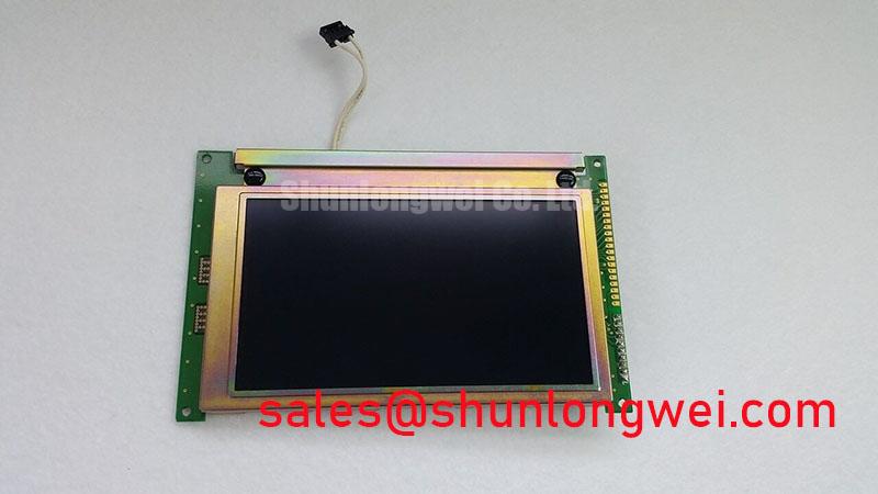
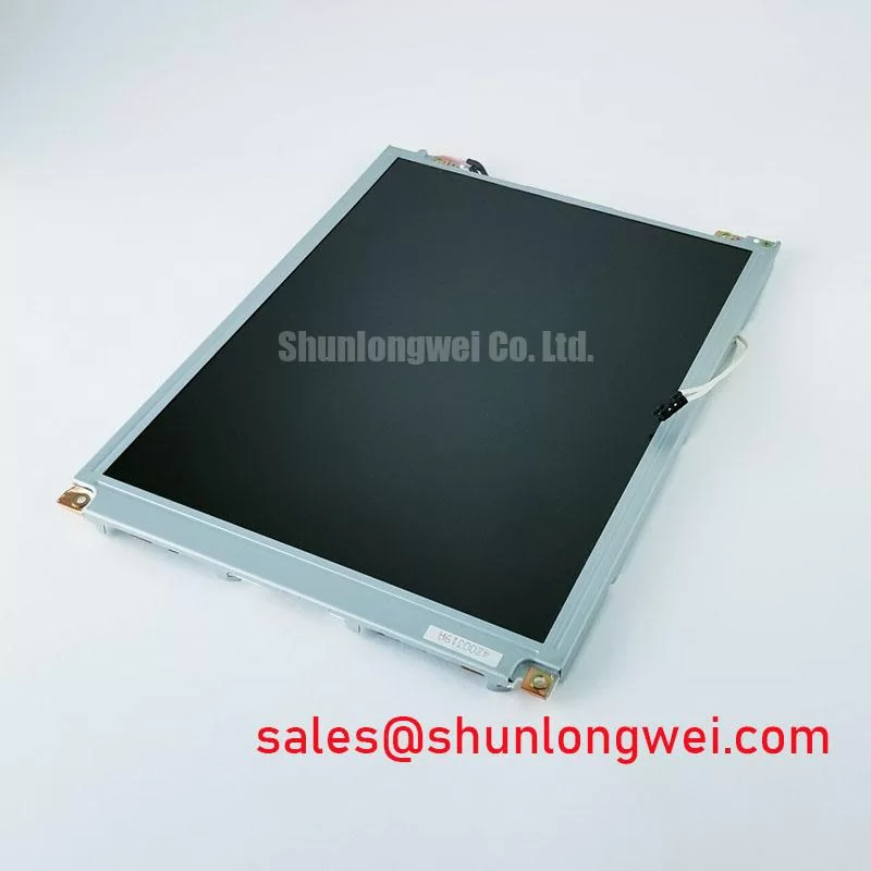
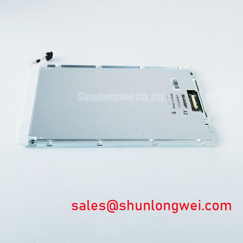
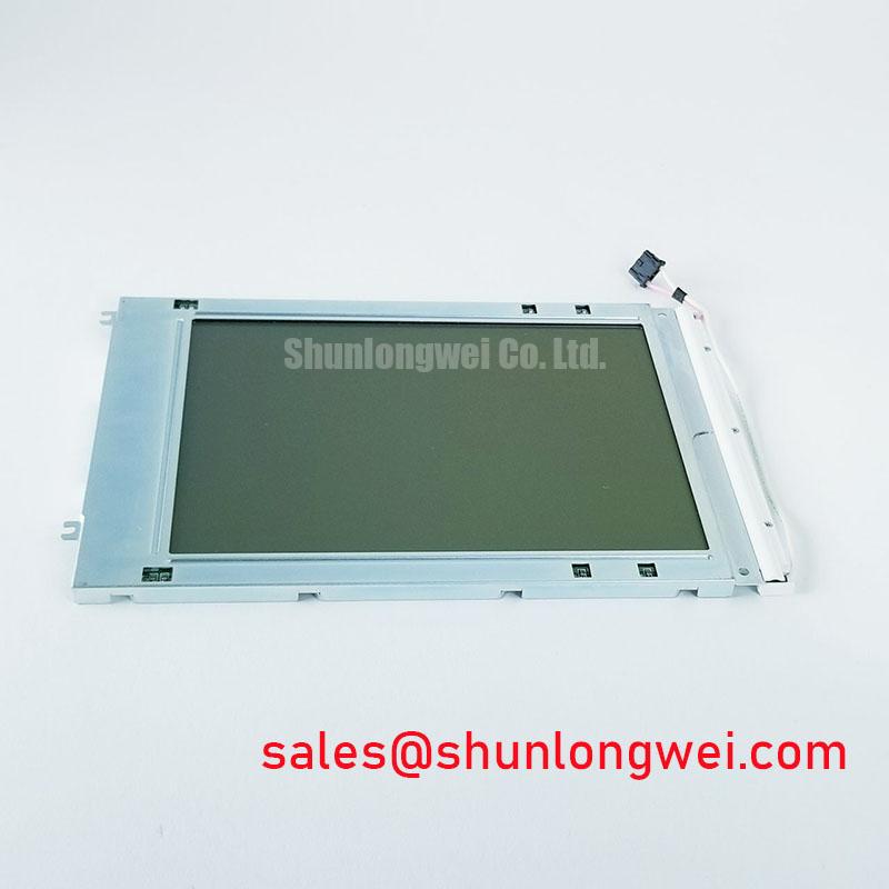
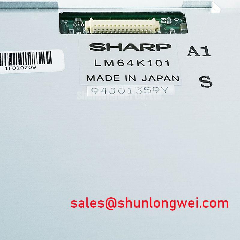
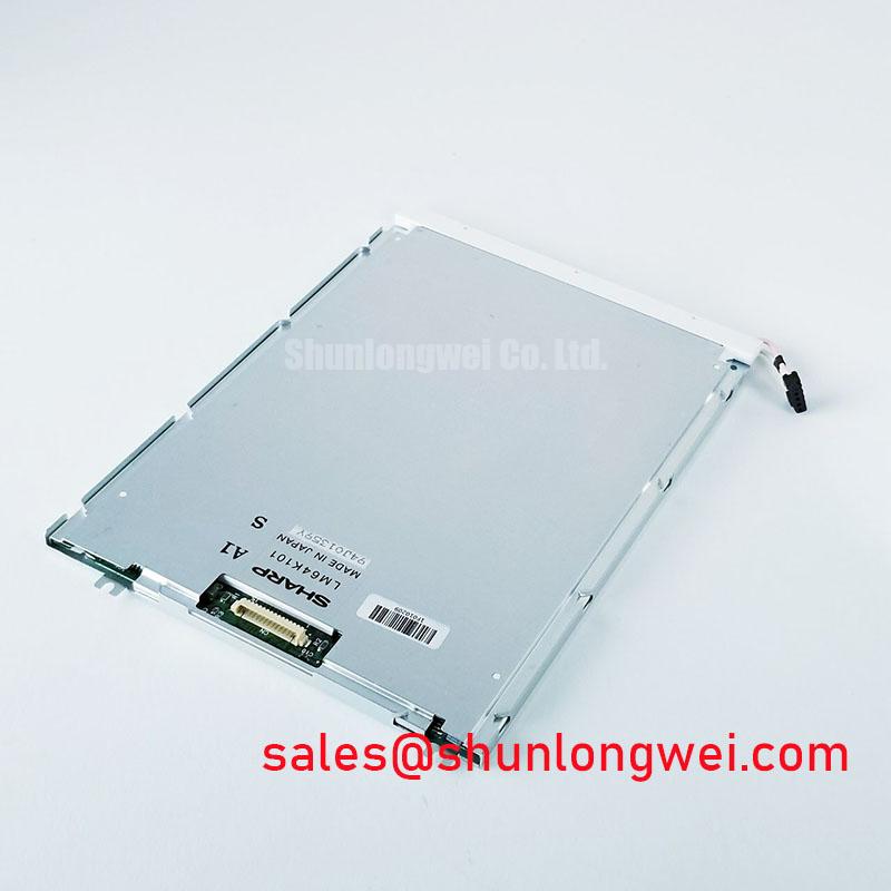
Begin the replacement check by isolating the display assembly, recording the existing connector orientation, and comparing the installed panel marking with LM64K101 before applying power. The available product record identifies this unit as a Sharp TFT LCD Display Module for industrial HMI use, with an official factory specification status but without a complete numeric interface, optical, or backlight table in the supplied data. System integrators should therefore verify the original panel documentation and machine wiring before installation.
| Parameter | Available specification status |
|---|---|
| Model | LM64K101 |
| Manufacturer | Sharp |
| Product category | Industrial Grade LCD/HMI Panel |
| Construction | TFT LCD Display Module |
| Specification status | Official Factory Spec Verified |
The exact resolution, active viewing area, connector pinout, logic supply voltage, display timing, interface type, backlight configuration, luminance, contrast ratio, and operating temperature range are not stated in the supplied factory parameter set. Those values should not be inferred from the model number. Before sourcing a replacement for an Automated Guided Vehicle or forklift telematics display, compare the original panel label, cable arrangement, controller output, mounting dimensions, and backlight power circuit.
Polarizer Durability and Optical Film Inspection under Direct Industrial Lighting
Inspect the polarizer surface under controlled ambient lighting before fitting the panel into an enclosure. Look for edge lifting, pressure marks, uneven haze, scratches, contamination, and localized color changes that become visible when the screen is viewed from different angles. These observations are practical screening checks rather than a substitute for the manufacturer’s optical qualification data.
TN, IPS, and MVA panels can exhibit different grayscale behavior and viewing angle characteristics. The supplied specification set does not confirm the optical mode used by LM64K101, so the replacement should be compared with a known working display at the actual operator position. Check dark gray, mid gray, warning colors, and high contrast symbols while viewing from the left, right, above, and below. A display that appears acceptable from the center may show luminance loss, color shift, or grayscale inversion when installed in a vehicle dashboard.
Direct sunlight creates a separate evaluation condition. The supplied information does not confirm a contrast ratio above 500:1 at 50,000 lux, nor does it confirm a particular anti glare treatment. Do not publish or design around those values as LM64K101 factory ratings without the original optical datasheet. Instead, assess the complete front assembly under the intended enclosure window, including reflections from protective glass, touch overlays, bezels, and dashboard surfaces.
Surface anti glare performance is also affected by viewing angle and the cleanliness of the cover. A matte surface may reduce mirror like reflections while changing apparent sharpness or black level. When the display is used in an AGV or forklift telematics panel, verify that status icons remain distinguishable when the vehicle moves between warehouse aisles, loading areas, and brighter outdoor zones. The system designer should determine whether an external cover, bonding layer, or visor changes the optical result.
Mechanical inspection should include the display frame, screw points, flexible cables, and connector retention. Do not press directly on the active area while checking fit. Confirm that the enclosure opening supports the panel without forcing the glass or bezel into a distorted position. If a same size or same resolution alternative is being evaluated, the LM64P10 should be compared through documented electrical, optical, and mechanical compatibility checks rather than treated as an automatic substitute.
💡 Pro Tip: Keep the pixel-clock and high-speed data paths physically controlled and as closely matched as the system layout permits, where applicable, then verify image stability with the display installed in its final cable and enclosure arrangement.
Diffuser Film and Prism Sheet Thermal Buckling Prevention under Continuous Full Duty Operation
Thermal inspection begins with the complete display assembly rather than the panel alone. Record the position of the driver electronics, backlight supply, enclosure vents, and nearby heat producing components. Uneven heating can change the appearance of diffuser or prism layers and may produce localized brightness variation, but the supplied LM64K101 data does not identify the internal optical film materials, LED lifetime rating, or thermal resistance.
For continuous operation, the enclosure designer should provide a stable mechanical support arrangement that avoids point loading at the display edges. Aluminum rails or heat spreading parts may be considered where the complete assembly produces localized heat, but their size, contact method, and placement must be established from measured temperatures and the panel’s mechanical drawing. They should not press against the active area or interfere with the original bezel and cable clearance.
The requested L70 or B50 backlight figures are not confirmed for this model. Similarly, a 50,000 hour half brightness value must not be assigned to LM64K101 without a manufacturer source defining test current, ambient temperature, drive condition, and failure criterion. If the panel is used in a vehicle terminal that remains powered for long periods, measure luminance drift and surface temperature under the actual brightness setting and enclosure condition.
Signal integrity should be examined at the panel connector and at the display controller. The supplied product record does not establish whether this model uses LVDS, TTL, or another interface. It also does not provide transmitter clock jitter limits, setup time, hold time, or data mapping. The integrator should verify the original interface documentation before changing a controller or cable. An apparent split image, unstable color, or intermittent line pattern can involve connector contact, cable routing, timing configuration, grounding, or supply behavior, so the signal path should be measured against a known good assembly.
Where the display is fitted to an AGV or forklift, cable movement deserves attention. Secure the harness so vibration is not transferred directly to the panel connector, while retaining enough service movement for removal. Keep the display cable away from switching nodes and high current motor wiring where practical. These are general design considerations, not Sharp factory requirements for this model.
Backlight power should be assessed as a separate circuit. The supplied data does not confirm whether this unit uses an LED backlight, CCFL arrangement, or a specific constant current input. The system integrator should verify the required backlight supply and dimming method from the original panel documentation. A replacement driver should only be connected after voltage, current, enable behavior, connector polarity, and fault response have been checked.
Logic Supply Voltage Sequencing and Driver IC Latch Up Risk
Before connecting a replacement panel, document the original power sequence with an oscilloscope or suitable logging instrument. Identify the logic rail, backlight enable, brightness control, reset signals, and image data activity as applicable to the installed system. The supplied factory information does not confirm whether LM64K101 requires 3.3 V, 5.0 V, or another logic supply, so the correct voltage must be taken from the original Sharp panel documentation or the equipment service documentation.
Applying an assumed supply voltage can damage the display electronics or create a misleading fault condition. Check the connector keying and pin numbering against the panel drawing rather than relying on cable color. Confirm the power rail behavior during startup and shutdown, including whether display data becomes active before the logic supply is stable. The values proposed in the requested timing range are not official LM64K101 specifications and should not be used as acceptance limits without a source.
Power down testing is equally important. A display that retains a pale image, shows a temporary white screen, or exhibits residual graphics may require investigation of discharge paths, controller timing, backlight enable behavior, or the host system’s shutdown sequence. These symptoms do not identify a single failed component. Compare the panel supply and control signals with a working unit while observing the complete startup and shutdown cycle.
Data format compatibility must also be confirmed. The supplied data does not state whether the panel expects JEIDA or VESA mapping, nor does it define the lane count, pixel clock range, color depth, or connector assignment. When replacing a controller, verify the mapping in the panel documentation and inspect the displayed color bars, grayscale ramps, and fine text. Incorrect mapping can present as color order errors, unstable graphics, or a split screen, but cable integrity and timing must also be excluded.
Differential routing should follow the controller manufacturer’s signal integrity guidance. The requested 100 ohm characteristic impedance is a general high speed interconnect consideration, not a confirmed LM64K101 factory requirement. The final cable and PCB arrangement should be evaluated as one channel, with attention to return paths, connector discontinuities, common mode noise, and cable length. An oscilloscope comparison at the panel end is more useful than judging compatibility from connector shape alone.
For a power topology review, the related LMS700KF01-001 may be examined as a separate display solution component. Its presence does not establish electrical compatibility with LM64K101, so voltage levels, control logic, connector definitions, and operating conditions still require independent confirmation.
Dual Channel CCFL High Voltage Resonant Inverter and Backlight Ignition Debugging
Do not assume a CCFL inverter architecture from the panel category alone. The supplied LM64K101 record does not confirm dual channel CCFL operation, cold ignition voltage, constant current LED drive, PWM dimming ratio, acoustic behavior, or backlight service life. Identify the installed backlight technology from the original equipment documentation and inspect the associated inverter or driver before selecting a replacement.
If the original assembly uses a high voltage fluorescent backlight, isolate the inverter and follow the equipment manufacturer’s discharge and access procedure. High voltage ignition measurements require appropriately rated probes, controlled test conditions, and protection against exposed conductive parts. The requested 1,500 to 1,650 Vrms ignition range is not an official LM64K101 rating in the supplied data and must not be used as a diagnostic limit for this model.
Ignition difficulty can involve the inverter transformer, lamp connection, insulation condition, control enable signal, supply stability, or the lamp itself. Audible noise may also be associated with mechanical vibration in the inverter or enclosure. Avoid assigning a single cause from a symptom alone. Compare the input supply, enable waveform, output behavior, and illumination uniformity with the known good equipment configuration.
If the machine has already been converted to an LED backlight, verify that the replacement driver matches the actual panel input arrangement. The supplied information does not confirm a 1,000:1 PWM dimming capability or a constant current operating specification. Brightness control should be checked for minimum level stability, startup behavior, electromagnetic interference, and interaction with the host HMI controller.
For AGV and forklift telematics installations, inspect the front seal, cable exit, mounting compression, and protective window after the display has been installed. Dust or moisture entering through the enclosure can affect optical clarity and connector reliability, but the available data does not confirm an optical bonding construction or an ingress protection rating for LM64K101. Any sealing method should be validated against the enclosure design and service requirements.
Long term static interface content also deserves a system level review. Fixed warning bars, logos, and status panels can create uneven visual aging depending on panel technology, luminance setting, temperature, and operating schedule. The supplied factory data does not provide an image retention or burn in guarantee. Designers should evaluate screen rotation, interface layout, brightness control, and service replacement criteria using the actual operating profile.
For broader integration guidance covering industrial display and HMI selection, interface checks, enclosure conditions, and field troubleshooting, consult Industrial Display & HMI Solutions. Any final replacement decision should be based on confirmed electrical, optical, mechanical, and backlight compatibility with the original equipment.