Content last revised on October 30, 2026
Sharp LQ104V1DG74 Display Identification and Initial Checks
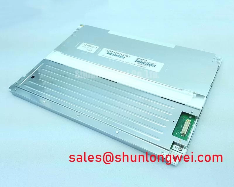
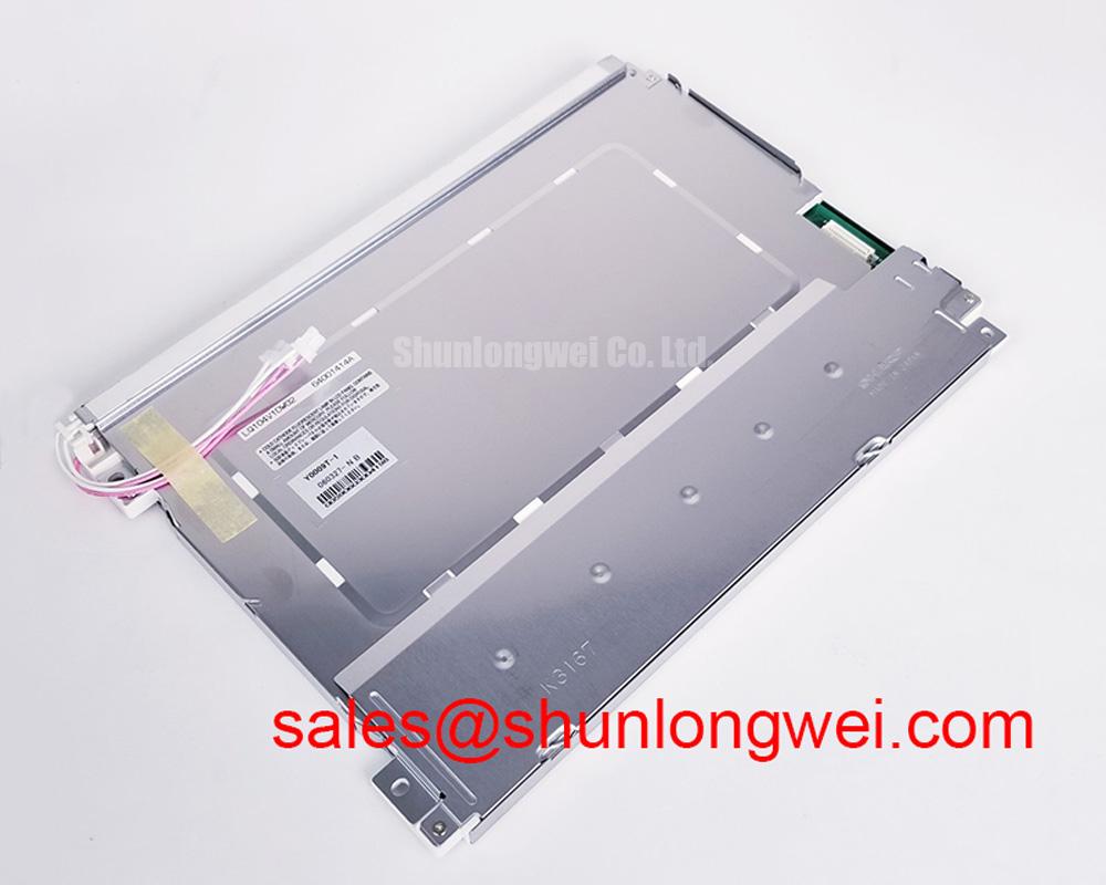
Disconnect the display harness with the equipment powered down, then check connector seating and the panel label before tracing a dark screen or unstable image on the Sharp LQ104V1DG74. Separate missing illumination from missing image data early: a screen that still forms a faint image needs a different investigation from one showing corrupted pixels or no recognizable graphics.
The LQ104V1DG74 LCD display has a 10.4-inch screen, 640 × 480 VGA resolution, and a CMOS, single-channel, 6-bit interface. These official specifications establish its basic integration identity; they do not describe an LVDS panel. The specified interface uses a 31-pin connection, making cable pin assignment and controller compatibility central to replacement assessment.
Industrial EMI Noise Immunity, Chassis Shielding Continuity & Common-Mode Ferrite Chokes
Correlate pixel jitter or horizontal bands with motor-drive activity before changing the display cable or adding suppression components. As a Design Consideration, compare the image with nearby switching equipment idle and operating under representative conditions. A repeatable relationship helps direct measurements toward conducted interference, radiated coupling, or disturbances on the controller supply, without treating the symptom as proof of a single cause.
Inspect the existing harness route, chassis bonding points, connector retention, and any shield termination. Where the equipment uses a shielded harness, preserve its intended chassis connection and avoid creating long, loosely routed shield connections during repair. Full-perimeter shield termination is an enclosure and harness design technique, not an established feature of this panel or a reason to modify its connector indiscriminately.
Common-mode ferrites are optional system-level mitigation components. Engineers should evaluate their placement and impedance characteristics against the measured disturbance spectrum, then check image stability and signal integrity after installation. A ferrite cannot compensate for an incorrect pinout, poor supply regulation, or an interrupted signal return. The panel’s CMOS connection must not be treated as an LVDS cable simply because both carry display data.
The official optical specifications are 350 cd/m² typical luminance and 600:1 contrast ratio. Neither establishes contrast under direct sunlight or confirms an anti-glare surface treatment. The distinction between panel contrast and ambient-light readability is explained in Contrast Ratio Measurement; evaluate the assembled display through its actual protective window under the intended lighting.
Full-Screen Primary Color AOI Screening: Stuck Sub-Pixels & Background Uniformity Audit
Display full-screen red, green, and blue patterns sequentially, inspecting each for persistent bright points, missing color contributions, and lines that remain fixed in position. Follow with white, black, and intermediate gray images to examine background uniformity and tonal transitions. This is a Design Consideration for bench screening, not a manufacturer-defined pixel acceptance standard.
For a dark display, direct a flashlight obliquely across the viewing surface while the controller presents a recognizable image. Faint visible graphics can help separate an illumination-path problem from complete loss of image formation. Check the backlight supply, enable control, and connections through the equipment’s documented service procedure. A persistent line alone does not establish an internal driver fracture; cable, controller, and panel faults can produce overlapping symptoms.
Record viewing position, ambient light, displayed pattern, and warm-up condition so comparisons remain repeatable. Do not assign IPS or MVA behavior to this model without supporting specifications. When considering the NL10276AC30-53D, use the following replacement checklist rather than assuming equivalence from its product category.
| Replacement criterion | Sharp LQ104V1DG74 | NL10276AC30-53D comparison requirement |
|---|---|---|
| Panel size | 10.4-inch, official specification | Consult datasheet; compare outline and mounting |
| Native resolution | 640 × 480 pixels, official specification | Consult datasheet; compare controller output |
| Signal interface | CMOS, single-channel, 6-bit; 31-pin connection | Consult datasheet; compare signaling and pin assignment |
| Optical performance | 350 cd/m² typical; 600:1 contrast ratio | Consult datasheet; compare measurement conditions |
| Operating temperature | −10 °C to +65 °C, official specification | Consult datasheet; compare operating limits |
A replacement decision also needs matching mechanical clearances, backlight connections, supply requirements, and timing. A shared diagonal size does not establish interchangeability.
Investigating Localized Thermal Gradients and Optical Color Shift
Map temperature around the installed display edges and nearby heat-producing electronics after the enclosure reaches a representative operating condition. The LQ104V1DG74 has an official operating temperature range of −10 °C to +65 °C. Evaluate the panel’s local environment rather than relying only on a cabinet sensor located away from the display.
As a Design Consideration, investigate whether restricted airflow, adjacent power components, or mounting pressure coincides with uneven brightness or color drift. Compare cold and warmed images using the same gray and white patterns. These observations can establish a temperature-related pattern, but they do not identify a particular internal optical material or prove permanent yellowing.
A chassis heat spreader can be considered where measurements demonstrate localized heating. Its material, dimensions, attachment, and electrical isolation belong to the enclosure design; verify that the arrangement does not distort the panel frame or load the viewing surface. Contact with a display edge is not automatically a useful thermal path.
Do not translate generic LED lifetime curves into an operating-life claim for this model. Brightness maintenance, failure rate, and backlight service life are different quantities requiring model-specific evidence and test conditions. For the broader relationship between illumination, thermal management, and display selection, The Ultimate Guide to Industrial TFT LCD Technology provides supporting context.
CMOS Interface Routing and High-Frequency Signal Integrity
Trace the controller output to the panel connector before applying differential-routing rules: the LQ104V1DG74 uses CMOS signaling, not LVDS. A 100-ohm differential-impedance target is therefore not a panel routing requirement. JEIDA/VESA LVDS mapping should not be substituted for the panel’s CMOS pin assignment.
As an Engineering Recommendation, compare the controller schematic and panel timing requirements for pixel clock, color-data allocation, synchronization, and signal returns. Investigate ringing, unstable logic levels, or clock-to-data timing at an appropriate measurement point when artifacts vary with harness position. Keep signal paths and returns consistent with the validated equipment design, and assess any cable change against receiver timing margins.
Field Alert: Power down and isolate the equipment before disconnecting or reseating the panel and backlight connectors.
Use the original panel electrical requirements to check supply levels, power sequencing, and backlight control behavior; do not assign generic voltage, rise-time, or dimming-frequency values. For railway passenger information or cab-signalling display replacement assessments, designers should additionally verify controller compatibility, enclosure readability, environmental requirements, and equipment-level approvals rather than infer suitability from VGA resolution. If grayscale remains distorted after interface checks, compare controller output and documented display settings before altering gamma-related circuitry.