Content last revised on October 14, 2026
Polarizer Durability & Optical Retardation Film Inspection under Direct Industrial Lighting
Under direct workshop lighting, I first drive a full-screen white, black, red, green, and blue test pattern across the TX23D88VM0AAA and inspect the viewing surface from normal and oblique positions. This exposes stuck pixels, uneven luminance, local haze, polarizer scratches, and optical areas that become visible only when reflections move across the panel.
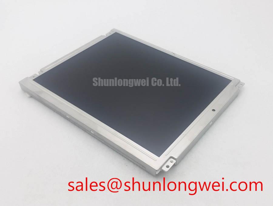
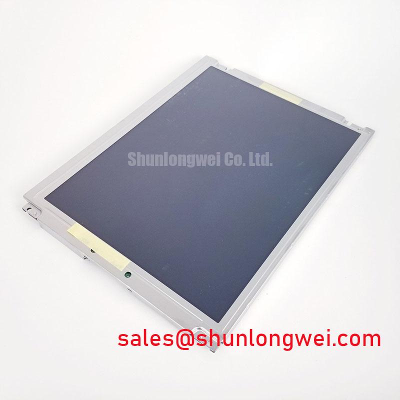
The product is identified as a KOE / Hitachi TFT-LCD Active Matrix Color Display Module for industrial LCD/HMI integration. The available information does not confirm a specific LCD cell mode, viewing-angle cone, resolution, backlight architecture, touch layer, or interface pinout. Those characteristics should be matched against the original equipment documentation before replacement approval.
TN, IPS, and MVA panels can show different grayscale behavior as the viewing angle changes. A technician should therefore compare gray ramps rather than relying only on a white screen. In a TN design, grayscale inversion may become visible above or below the intended sightline; IPS or MVA products can provide a more symmetrical viewing response, but that property must not be assigned to this model without a supporting manufacturer specification. The viewing angle characteristics reference provides useful background for interpreting these changes.
Surface treatment also matters in precision electronic test and measurement instruments. An anti-glare surface can reduce reflected overhead lamps, while a glossy or differently etched surface may preserve more apparent contrast but reveal bright reflections. Compare the replacement panel with the removed unit under the same lamp position. Look for circular glare, rainbow-like retardation effects, and contrast loss near the edge of the viewing field rather than judging optical quality from a central image alone.
For signal validation, identify whether the host uses TTL or LVDS before connecting test equipment. Measure transmitter clock stability, data hold behavior, and frame continuity across the equipment’s specified operating temperature window, staying within the panel’s documented limits. The panel listing does not establish a model-specific clock rate or hold-time limit, so the acceptance limit should come from the original controller and panel documentation. The Winstar TFT-LCD reference is useful for comparing the terminology used in industrial display specifications.
Eye-Diagram Voltage Margin & Differential Noise Floor Verification in High-Vibration Bays
Pixel jitter and horizontal noise bands should be examined while the display cable is installed in its final routing position, especially when the instrument shares a cabinet with switching supplies or variable-frequency motor drives. If the interface is differential, capture the differential signal at the receiver side where practical, then compare the eye opening and common-mode movement with a known-good assembly.
A 360-degree shield termination is a Design Consideration, not a confirmed feature of this display module. The shield and signal-return strategy should be decided by the system EMC engineer so that high-frequency currents do not flow through sensitive logic returns. Ferrite suppression can also alter the common-mode response; its suitability depends on cable construction, interference frequency, grounding topology, and the driver and receiver characteristics.
Vibration testing should include a gentle cable movement check while the panel is displaying fine vertical lines and gray ramps. A loose FFC, uneven insertion, or connector latch movement may appear as intermittent noise rather than a permanent blank screen. Do not diagnose the display cell from that symptom alone. Correlate the image disturbance with the measured link waveform, connector retention, and power-rail behavior.
Backlight assessment must be separated from LCD image assessment. If the image remains visible under controlled illumination while the screen appears dark, inspect the backlight driver output, current regulation, open-load response, and short-circuit protection at the system level. The available product parameters do not confirm a model-specific backlight lifetime, protection threshold, or LED configuration. A claimed 50,000-hour brightness point should only be used when it appears in the applicable panel or backlight datasheet; it should not be transferred from another display family.
💡 Bench Tip: Power down the instrument before inserting or removing the FFC, protect the connector area against ESD, and confirm that the cable is fully square before closing the lock.
Controlled 100-Ohm Differential Impedance Flex Routing to Suppress High-Frequency Jitter
When the host uses a differential display link, route the flex cable without sharp folds, pressure points, or unnecessary loops near high-current switching paths. A nominal 100 Ω differential impedance is a general Design Consideration for many high-speed links, not an official electrical rating established here for the TX23D88VM0AAA. The actual target must follow the controller, cable, and receiver interface documentation as one complete channel.
Check the logic supply requirement from the original panel documentation rather than assuming a generic rail. The available product information does not confirm whether this unit uses a particular logic voltage, so the integrator should verify the voltage, enable sequence, reset behavior, and backlight control signals before applying power. Observe the rise sequence with an oscilloscope and confirm that the panel does not receive data before its required logic and enable conditions are satisfied.
For an LVDS interface, JEIDA and VESA mappings are not interchangeable assumptions. A mapping error can create incorrect colors or grayscale levels even when the cable is physically compatible. Record the data-pair order, clock polarity, bit mapping, and connector orientation from the original assembly, then compare those details with the replacement documentation.
Cold testing deserves a separate optical check. Liquid-crystal response can become visibly slower as ambient temperature falls, producing gray-to-gray smearing or delayed transitions. If the equipment uses a cabinet heater or controlled enclosure, treat that hardware as a system-level accessory rather than a confirmed part of this module. Measure the image transition, panel surface temperature, and supply stability together so that response lag is not confused with link errors.
For a neutral replacement comparison, engineers evaluating a different industrial TFT form factor can review TX18D216VM0BAA. Mechanical outline, optical performance, connector position, and electrical timing still require a direct compatibility check; a similar product category does not establish interchangeability.
Preventing Frame Lag & Image Smearing in Cold-Storage & Outdoor Industrial Facilities
For sub-zero testing, first verify that the intended temperature is within the panel’s documented operating range; cryogenic operation must not be assumed. Begin with a moving test pattern and a gray transition sequence rather than a static logo. Slow liquid-crystal response can produce trailing edges, while a marginal differential link may create intermittent frame errors. The two conditions require different observations: optical lag follows the moving image, whereas transmission faults often alter line structure, synchronization, or frame content.
Thermal cycling should be performed within documented temperature limits with the panel mounted as it will be used. Watch the perimeter, viewing surface, connector region, and mounting points for stress marks, delamination-like optical changes, or image recovery after the temperature returns to ambient. Do not attribute sealant performance, optical film durability, or thermal limits to this model unless those properties are stated in its applicable manufacturer documentation.
In high-EMI factory environments, differential-pair routing should preserve a controlled return path and consistent geometry. A commonly used engineering target is 100 Ω differential impedance with a tightly controlled pair skew, but the system designer must set the final tolerance from the transmitter, cable, receiver, and measurement method. The practical objective is to reduce reflections and timing uncertainty while verifying the eye opening at the receiving device.
For installation in a precision electronic test instrument, compare the replacement image at startup, during long waveform display, and while adjacent equipment changes operating state. Inspect the backlight separately for flicker, uneven illumination, or driver shutdown. If a touch layer is present in the equipment, verify its controller, overlay construction, glove response, and wet-finger behavior independently because the available product classification identifies an LCD/HMI panel, not a confirmed touch specification.
For connector handling, optical acceptance, and interface troubleshooting principles, consult The Ultimate Guide to Industrial TFT-LCD Technology alongside the original equipment service documentation.