

Content last revised on October 17, 2026
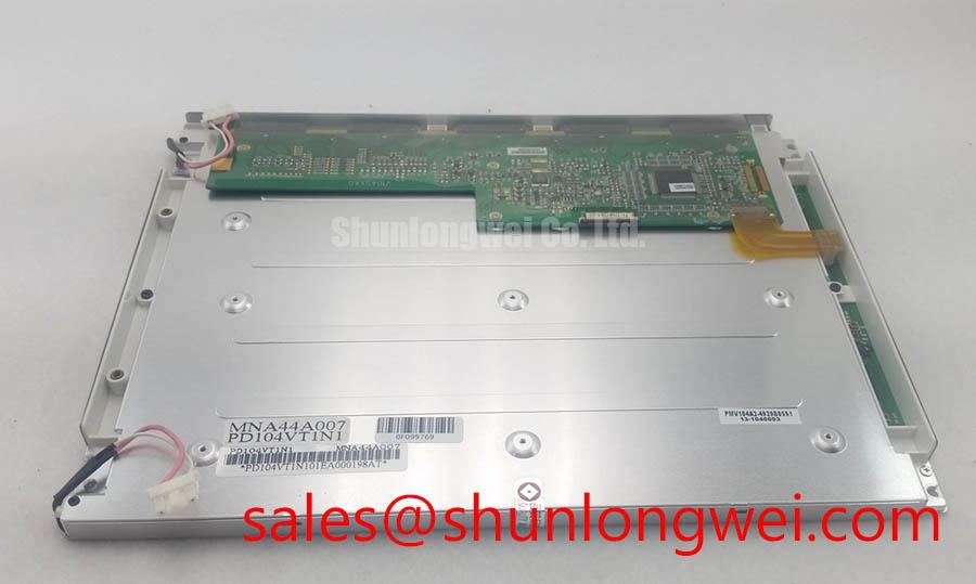
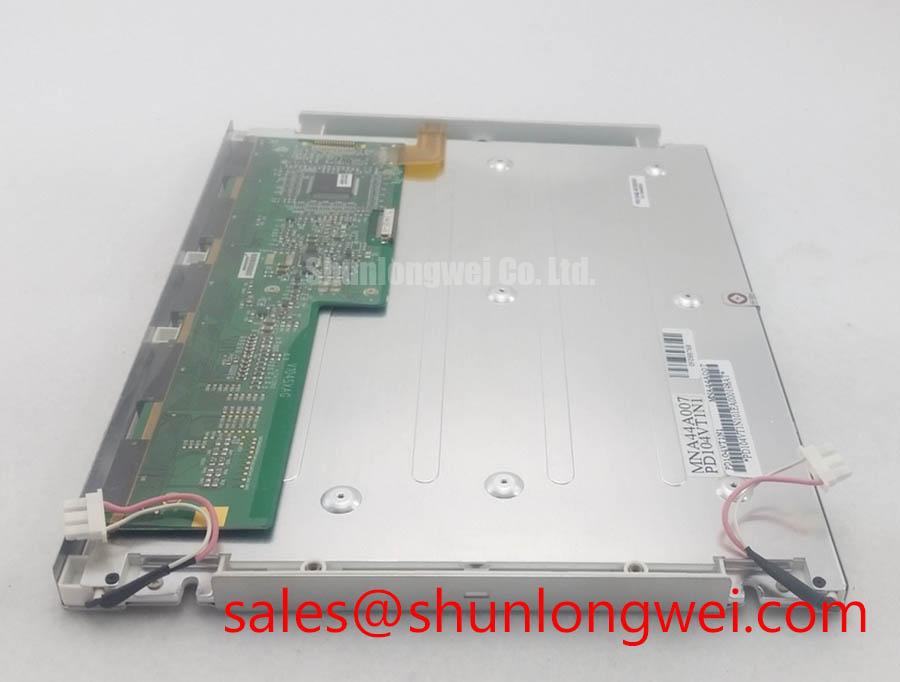
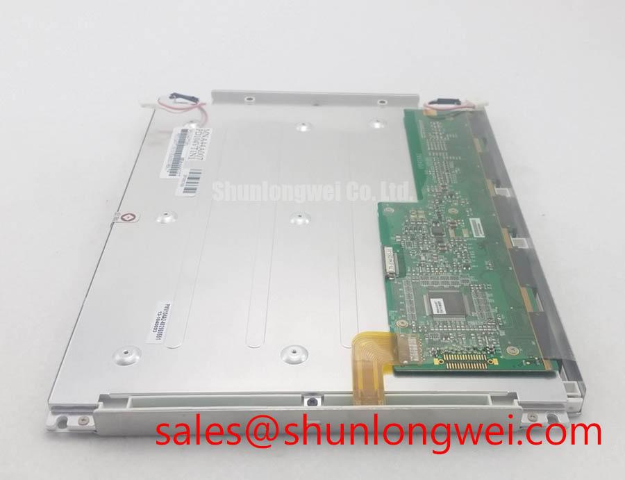
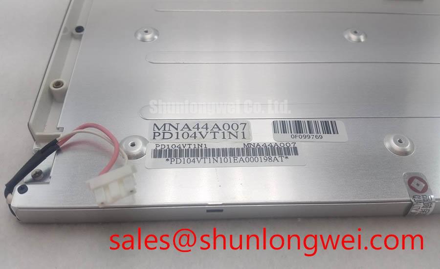
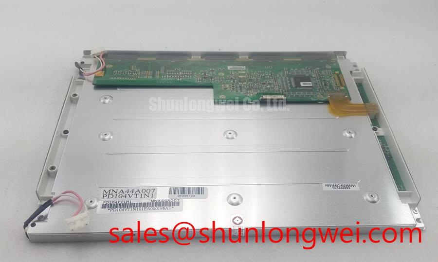
PD104VT1N1 PVI Industrial TFT LCD Display Module
- Confirm the installed panel identification against PD104VT1N1 before removing the existing display.
- Check the display connector, cable routing, grounding path, and enclosure clearance before applying power.
- Inspect the mounting frame for uneven pressure that could distort the active matrix panel.
- Verify the original equipment documentation for supply voltage, signal timing, backlight control, and mechanical dimensions.
The PD104VT1N1 is a PVI (Prime View International) TFT LCD active matrix color display module that may be evaluated as a replacement or service component in industrial control equipment. Suitability depends on the original equipment's electrical, mechanical, and environmental requirements.
| Model | PD104VT1N1 |
| Manufacturer | PVI, Prime View International |
| Product category | LCD Display |
| Module type | TFT LCD Active Matrix Color Display Module |
The system integrator should verify the required supply voltage and current from the original panel documentation and confirm the controller interface before installation. Do not infer a replacement supply setting from the model number alone.
Preventing Display Disturbances in PD104VT1N1 Installations
For a medium frequency induction melting or hardening furnace, a compatible display may be used at the operator interface or monitoring panel while a separate controller manages the firing circuit. A service engineer should trace the display supply and signal cable back to the control board, separating it from high current thyristor conductors and rapidly switching power loops where the equipment layout permits. This reduces the possibility that display disturbances are mistaken for a gate firing fault or that a control fault is incorrectly attributed to the LCD module.
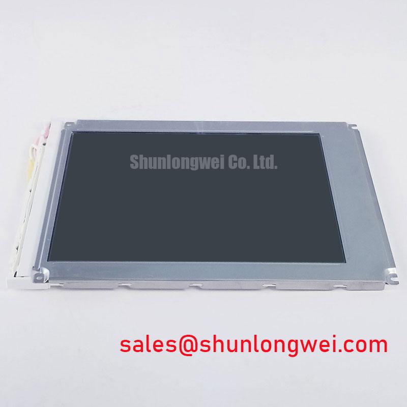
Terminal work should follow the original equipment wiring diagram. Check connector orientation, contact retention, cable shielding, and chassis bonding before energizing the system. If the control board has been replaced, compare the known good display signal path with the repaired assembly using the equipment service documentation. The TM104SDH03-03 may be reviewed as a separate display reference, but it should not be treated as an automatic electrical substitute for the PD104VT1N1.
Service caution: Disconnect equipment power and wait for the system discharge procedure to finish before unplugging or inserting the display cable.
When a display becomes intermittent during furnace operation, inspect the complete control chain rather than assigning a single cause to the panel. Compare the display supply at the panel connector, inspect the cable while the equipment is safely inactive, and check whether the fault follows the display, cable, controller, or power supply. A waveform comparison against a known good control channel can help identify signal integrity problems without treating the LCD module as a power switching device.
PD104VT1N1 Operational Boundaries: Thermal and Mechanical Considerations
The practical thermal assessment is mechanical and environmental. Confirm that the panel is mounted in a frame that supports the specified installation points without pressing directly against the active viewing area. Uneven frame pressure can produce visible nonuniformity or intermittent behavior, while excessive enclosure temperature can affect the complete display assembly and its controller. The original panel documentation remains the reference for allowable temperature, storage conditions, and timing performance.
For cold-start evaluation, allow the complete control cabinet to reach the target test condition before recording image response, backlight behavior, and controller communication. If the system specification calls for industrial wide temperature operation, the engineer should verify the actual display temperature range and cold-start response from the applicable panel documentation rather than transferring a rating from another PVI model.
If the furnace control unit provides PWM brightness control, verify the required backlight interface, enable logic, current regulation method, and frequency compatibility before connecting it to the display. Do not connect an assumed LED or CCFL source without confirming the original panel architecture.
Mechanical vibration and shock should be evaluated at the enclosure level. Use a rigid but appropriately supported panel frame, prevent cable connectors from carrying mechanical load, and provide controlled cable routing near the display connector. For equipment with substantial vibration from cooling fans, pumps, or busbar assemblies, compare the panel image and connector continuity during a controlled equipment test. This approach separates mounting stress from controller or supply disturbances.
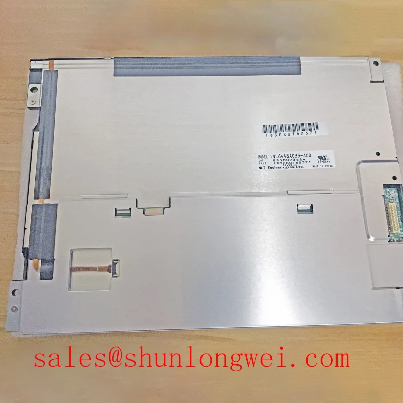
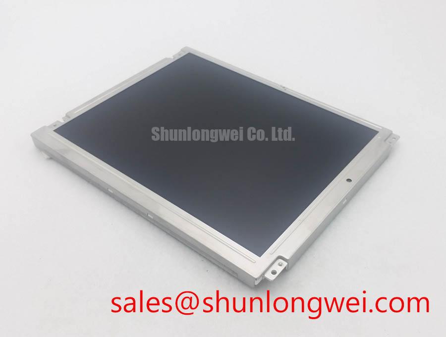
A separate display reference, LB104S02-TD01, can assist a sourcing engineer when comparing panel format and system documentation. It is a reference for evaluation only; connector pinout, optical characteristics, timing, backlight arrangement, and mechanical fit must be checked independently before any substitution decision.
Assembly Integrity and Layout: Managing Transients Around the PD104VT1N1
AC input surge protection, MOV selection, and RC snubber design are system-level considerations for the furnace power converter. The display should be protected by the equipment power architecture and by the controller interface provided by the original system. Its module description does not establish an AC input rating, surge withstand rating, EMC certification, or independent protection threshold.
During cabinet troubleshooting, inspect whether the display supply is derived from a protected control power branch rather than directly from a furnace switching node. The protection network should be evaluated by the system designer against the actual installation category, cable length, switching energy, and transient environment. IEC 61000-4-5 surge immunity testing may be relevant to the complete equipment assembly, but it does not constitute a standalone certification claim for this LCD module.
Keep high energy AC conductors, rectifier wiring, and thyristor gate leads physically separated from the display cable where the cabinet structure allows. Route the display signal cable with a continuous and intentional return path, avoid unnecessary loops, and secure the cable so vibration cannot pull on the connector. If a snubber, MOV, or auxiliary filter is added to the furnace controller, confirm that its leakage current and switching behavior do not disturb the low voltage display supply.
At commissioning, record the display supply behavior during controller startup, furnace enable, power interruption, and controlled shutdown. Observe whether the panel loses image, resets, dims, or remains stable as the power stage changes state. These observations help distinguish a display interface issue from a control supply transient. Any replacement cable or controller should be checked for pin compatibility and power sequencing before full equipment operation.
For broader power conversion context, the Wide Bandgap Revolution reference discusses switching technology and system design considerations. Those power semiconductor principles may influence the surrounding furnace converter, but they do not add unlisted electrical or thermal specifications to the PD104VT1N1 display module.