

Content last revised on September 14, 2026
Optical Luminance Degradation Curve and CCFL to LED Modernization Retrofit Pathways
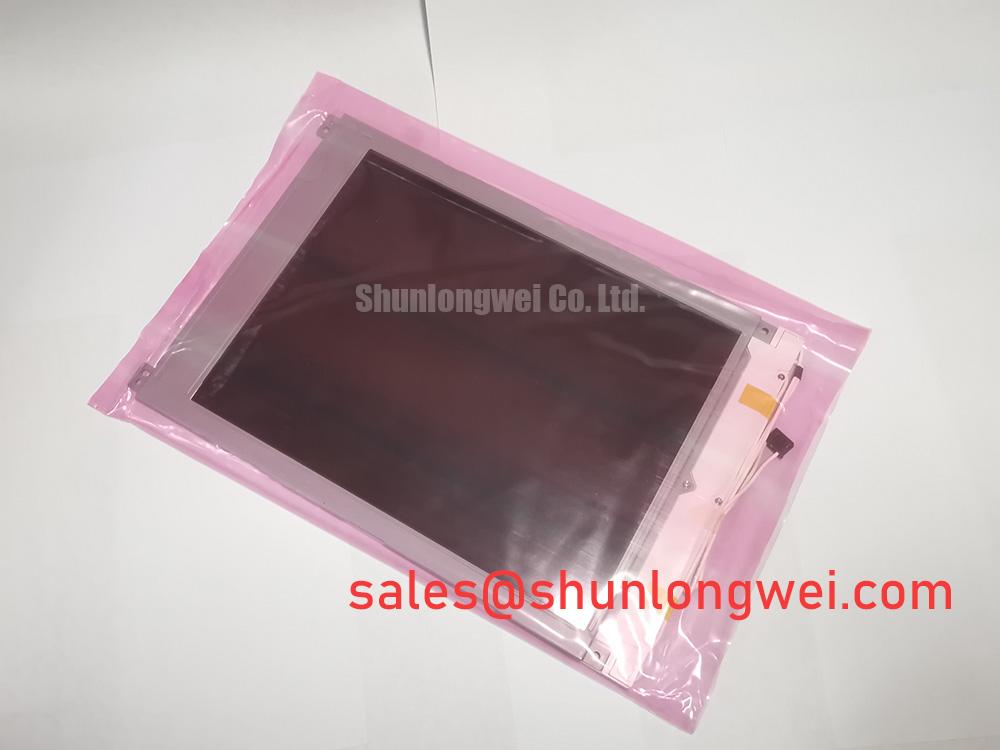
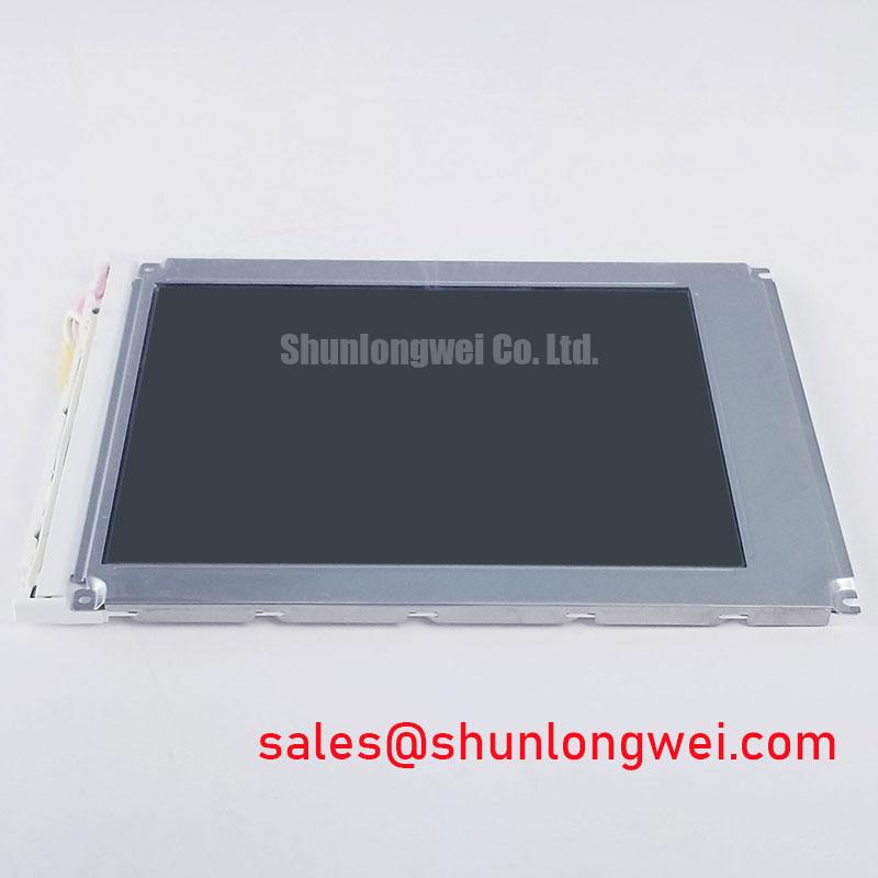
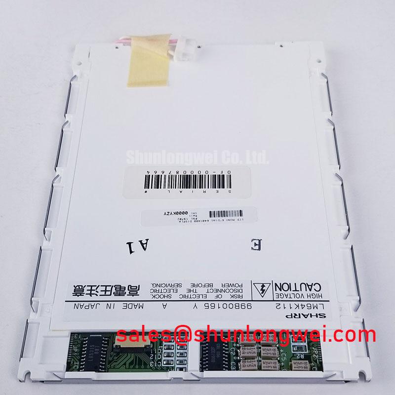
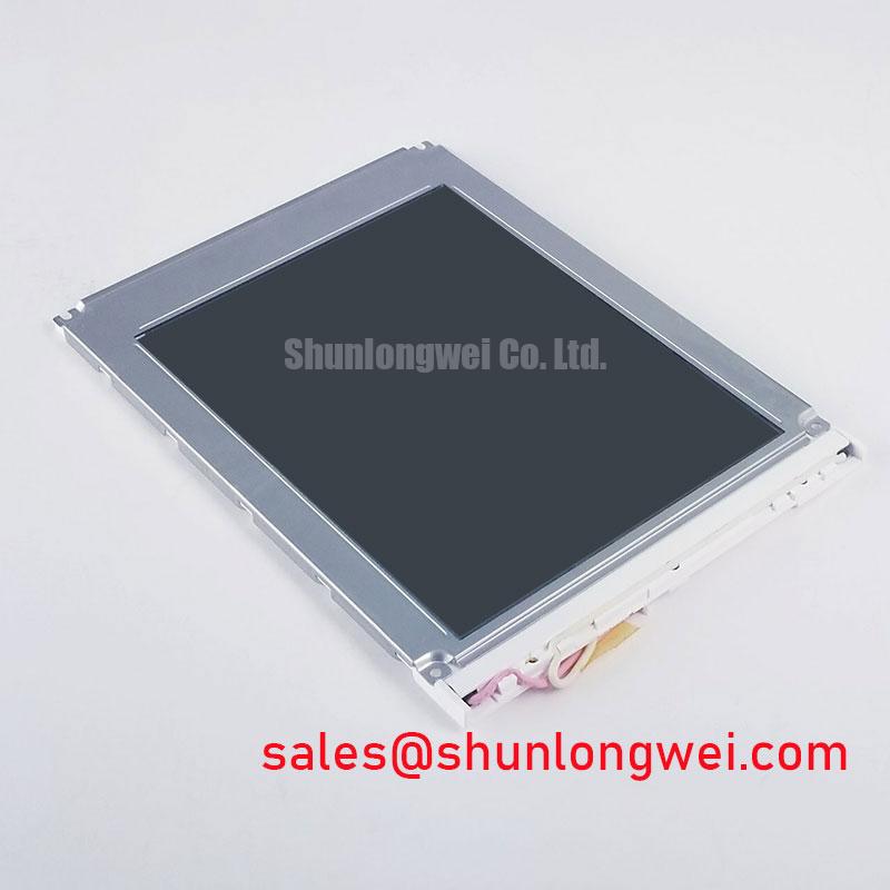
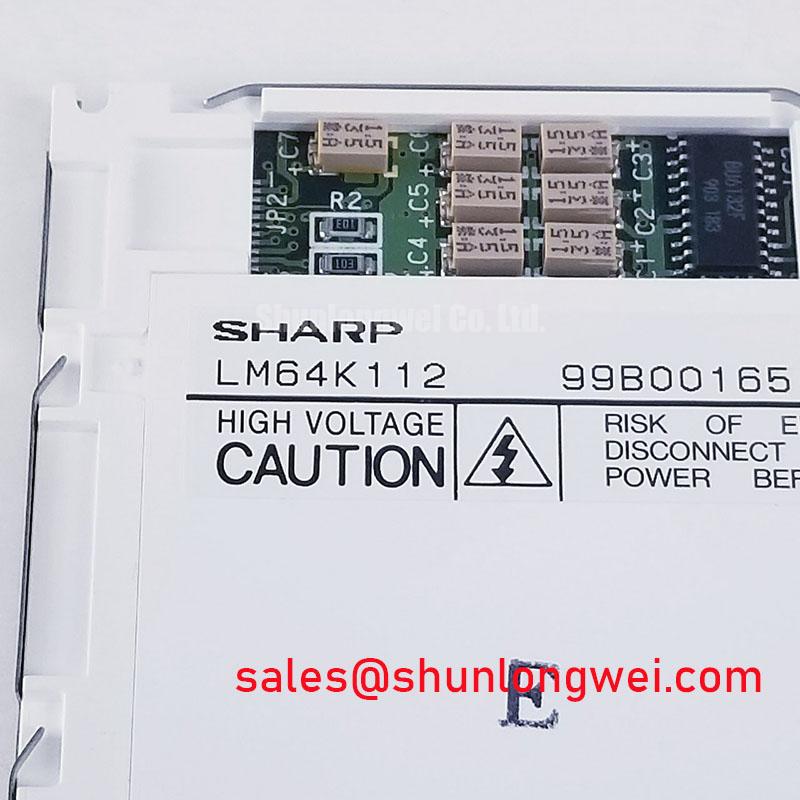
Begin the service check by isolating power, inspecting the display module for cracked glass or frame distortion, and comparing the installed connector arrangement with the original equipment documentation. The LM64K112 is identified in the supplied factory context as a Sharp TFT LCD Display Module for industrial LCD and HMI panel applications.
The available factory data identifies the product category, manufacturer, and module construction, but it does not provide a verified electrical interface table, native resolution, active area, luminance rating, contrast ratio, backlight type, supply voltage, connector pinout, operating temperature range, or mechanical drawing. Those values should be taken from the original Sharp documentation or the equipment service manual before installation. The system integrator should verify the required supply voltage from the original panel documentation rather than assume a value from a visually similar display.
| Parameter | Verified information |
|---|---|
| Model | LM64K112 |
| Manufacturer | Sharp |
| Product category | Industrial Grade LCD/HMI Panel |
| Module construction | TFT-LCD Display Module |
| Product identity status | Identified in the supplied factory context |
| Interface and electrical ratings | Verify against the original Sharp documentation |
| Mechanical dimensions and mounting pattern | Verify against the equipment drawing and removed unit |
Before planning a backlight retrofit, record the display’s existing optical behavior at startup, during warm operation, and after a prolonged static image. A dim screen does not by itself identify a failed panel. The backlight assembly, inverter or driver, cable connection, optical stack, control signal, and panel electronics should be assessed separately.
The supplied factory context does not confirm whether the LM64K112 uses a CCFL assembly, an LED backlight, a specific ignition voltage, a defined dimming method, or a manufacturer-rated half-life. Therefore, values associated with high-voltage CCFL ignition, constant-current LED operation, PWM dimming, brightness half-life, or MTBF must not be assigned to this model without the applicable Sharp document. A retrofit may be technically possible in some equipment, but it is a system modification rather than a confirmed native feature of the LM64K112.
For a CCFL-based assembly, a technician can inspect the inverter harness, lamp connectors, and startup waveform using equipment rated for the circuit. For an LED-based assembly, the relevant checks normally move toward driver enable behavior, current regulation, fault reporting, and the integrity of the LED harness. The original panel documentation should determine which test path applies. Substituting a driver with a different control polarity or dimming protocol can produce a dark screen, unstable brightness, audible noise, or repeated protection shutdown.
Low-temperature operation deserves a separate evaluation. Liquid crystal response can become visibly slower in cold environments, while condensation can affect connectors, coatings, and the surrounding HMI enclosure. A heater strip, if present in the equipment, should be controlled by the system designer according to the enclosure’s thermal and condensation analysis. The LM64K112 product data supplied here does not establish a specific cold-start limit or heater-control requirement.
For a potential harsh marine radar or navigation bridge console application, the installer should verify sunlight readability, enclosure sealing, salt-laden air protection, connector compatibility, and the thermal path around the module. These are integration conditions, not confirmed ratings of the display itself. Optical performance should be measured on the actual assembly with the intended cover glass, bezel, and ambient-light conditions.
Single Vertical Hairline Defect and Sub-Pixel Column Driver Open-Circuit Localization
A single vertical line should be investigated without flexing the glass or pressing the active area. Start with a controlled image test using full-field red, green, blue, white, black, and mid-level gray patterns. Observe whether the line remains fixed in position, changes with the image, or disappears when the signal source is replaced with a known-good test source. This color-field test is a practical diagnostic method, not a factory acceptance limit for the LM64K112.
A fixed line across several primary-color fields may justify inspection of the panel-to-driver connection, the display cable, and the source timing path. A line that appears only with one color or gray level may require closer analysis of data transmission, connector contact, or panel drive behavior. These observations can narrow the test area, but they do not prove a single failure mechanism.
An angled flashlight inspection in a darkened service area can help separate an optical surface mark from an electrically active line. A reflection, coating irregularity, or pressure mark may change with viewing angle, whereas an electronic line generally follows the same screen coordinate. This method is qualitative. It should be followed by comparison with a known-good module or signal path where available.
Do not use unsupported brightness-life or LED MTBF curves to determine whether this model has reached end of life. The supplied factory information does not publish a 50 percent brightness point, a backlight service-life figure, or a field failure rate for the LM64K112. If long-term brightness loss is suspected, measure the complete display assembly under a defined test condition and record the driver state, optical environment, and temperature.
Connector reliability is often overlooked during replacement work. The flexible cable should enter the connector along its intended axis, with the locking bar fully engaged and no sharp crease at the cable exit. The original bend path should be photographed before removal. A cable that is trapped under a bezel or forced against a metal edge can create an intermittent image fault without leaving an obvious external mark.
Maintenance Note: Disconnect power before removing or reseating the display cable, and inspect the enclosure’s cooling path and sealing gasket during every service intervention.
Preventing Localized Optical Nonuniformity from Mounting Pressure
Dark-field inspection is useful after the module has been mounted in its final bezel. Use a uniform black or low-level gray image and view the screen from the normal service position before changing any fastener. Bright patches, dark corners, or uneven areas can originate in the display assembly, cover window, bezel pressure, cable routing, or ambient reflections. The observation should be repeated with the panel removed from the chassis when the mechanical design permits.
The supplied LM64K112 information does not include a verified outer-bezel envelope, mounting-hole drawing, light-guide construction, allowable compression, or fastener torque specification. Consequently, a specific M3 torque limit or chassis tolerance must not be presented as an official value for this model. The mechanical drawing for the exact assembly should control the installation. As a general Design Consideration, fastening should distribute load evenly, avoid point pressure on the active area, and allow the display frame to sit naturally without being twisted by the enclosure.
Cross-pattern tightening is a useful general installation practice when a panel has multiple fasteners, because it can help release uneven mechanical stress. The correct sequence and torque remain system-determined and should be validated against the bezel material, threaded insert, gasket design, and original service instructions. Do not compensate for a poor fit by tightening one corner harder than the others.
Dust and moisture management begins at the interface between the display frame and the cabinet. The gasket should be continuous, clean, correctly seated, and free from compression damage. Any optical bonding, cover glass, anti-glare layer, or sealing compound must be confirmed from the original assembly documentation; none of these construction details is established by the supplied LM64K112 factory parameter set.
Signal integrity also belongs in the mechanical review. A cable routed beside a noisy power path may experience coupling, while excessive movement at the connector can disturb clock and data quality. The documentation should be checked to determine whether the module uses TTL, LVDS, or another interface. Clock jitter tolerance, data hold time, lane assignment, and termination requirements must come from the verified interface specification rather than from the appearance of the connector.
For replacement planning, LM64P10 may be reviewed as a separate compatible-device candidate when its dimensions, resolution, interface, optical performance, and mounting arrangement are confirmed against the host equipment. This is a neutral evaluation reference, not a universal substitution recommendation.
Radiated Emissions Evaluation and Backplate Grounding Around Variable-Frequency Drives
When a display is installed near a variable-frequency motor drive, first separate image-generation faults from electromagnetic interference. Compare the screen with the motor drive disabled, then observe the signal path, display supply, cable routing, and enclosure bonding under controlled operating conditions. Pixel jitter, horizontal bands, or intermittent loss of image can have several possible sources, including signal integrity, grounding, power disturbance, connector contact, or the display electronics.
The LM64K112 itself must not be described as independently compliant with CISPR Class A or Class B equipment limits. EMC performance belongs to the complete installation, including the host controller, cable harness, cabinet, power supply, grounding structure, enclosure, and external loads. The supplied product information does not provide an EMC certification, emissions profile, or immunity result for this module.
As a Design Consideration, keep high-current switching conductors physically separated from display signal wiring and avoid unnecessary cable loops. Where the interface uses shielded FFC or LVDS cabling, the system designer should verify the shield termination method, connector compatibility, and chassis bonding arrangement. A multi-point grounding strategy may be appropriate for the completed enclosure, but its effectiveness depends on the cabinet geometry and frequency range; it should be verified by measurement rather than assumed.
Common-mode ferrite components can be evaluated when conducted or radiated noise is traced to a cable path. Their impedance behavior, placement, current rating, and effect on signal quality must be selected from measured interference characteristics. Adding a ferrite without checking the interface waveform can alter edge quality or fail to address the actual coupling route.
Direct sunlight evaluation also requires the complete optical stack. The factory data supplied for the LM64K112 does not specify contrast ratio, luminance, anti-glare coating, viewing angle, color-shift behavior, or performance at a defined illuminance. For a marine radar or navigation bridge console, designers should test the display behind the intended window and bezel, with the final backlight setting and expected solar loading. Wide-view optical behavior, including angle-dependent color change, should be verified on the actual module rather than inferred from the TFT category.
Power sequencing should be checked at the host-system level. Confirm the order and timing of the display supply, logic supply, enable signals, reset behavior, and video transmission from the original documentation. White-screen startup, residual images, or delayed synchronization may involve the controller and timing source as well as the panel. When evaluating enclosure-level performance and service procedures, engineers can use Industrial Display and HMI Solutions as a practical reference alongside the exact equipment drawings and verified panel documentation.
The Sharp LM64K112 should therefore be integrated as an identified TFT-LCD Display Module only after the host system confirms its electrical interface, mechanical fit, optical requirements, environmental exposure, and service access. The documented product identity supports procurement and replacement screening; the remaining integration limits must be established from the original technical documentation and measured on the completed equipment.