Content last revised on September 21, 2026
6MBP160VCA060-51 Thermal-Electrical Optimization: Thermal Time Constants and Peak Junction Practical Tuning
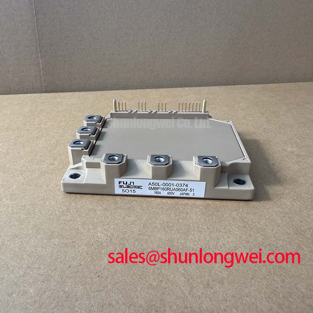
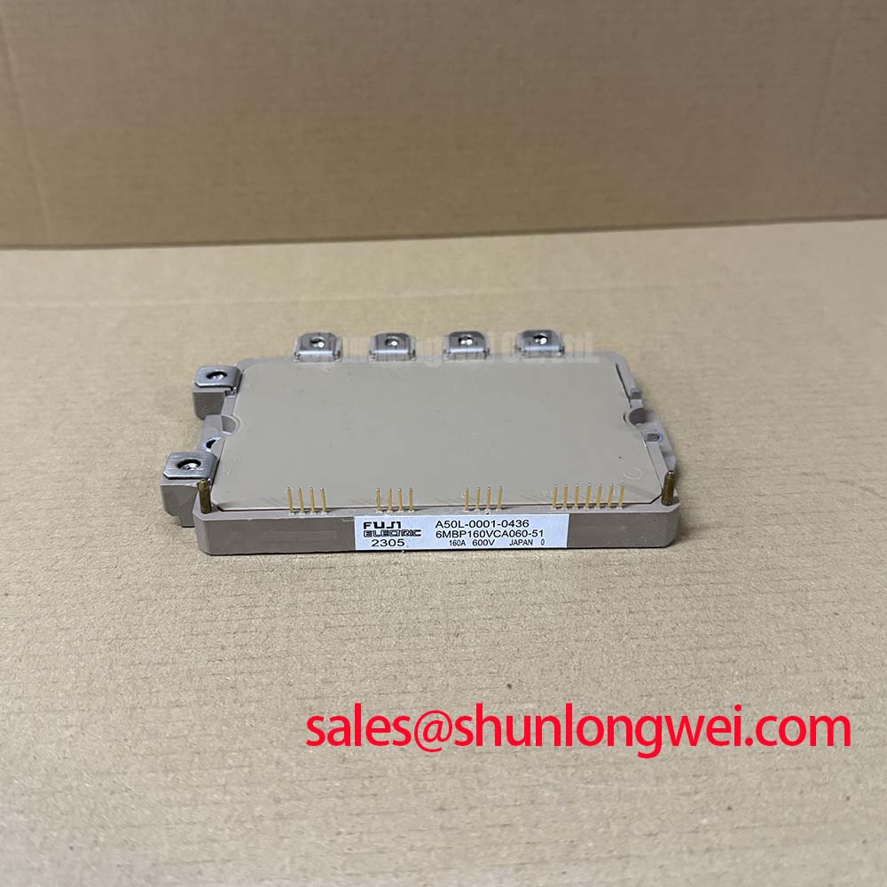
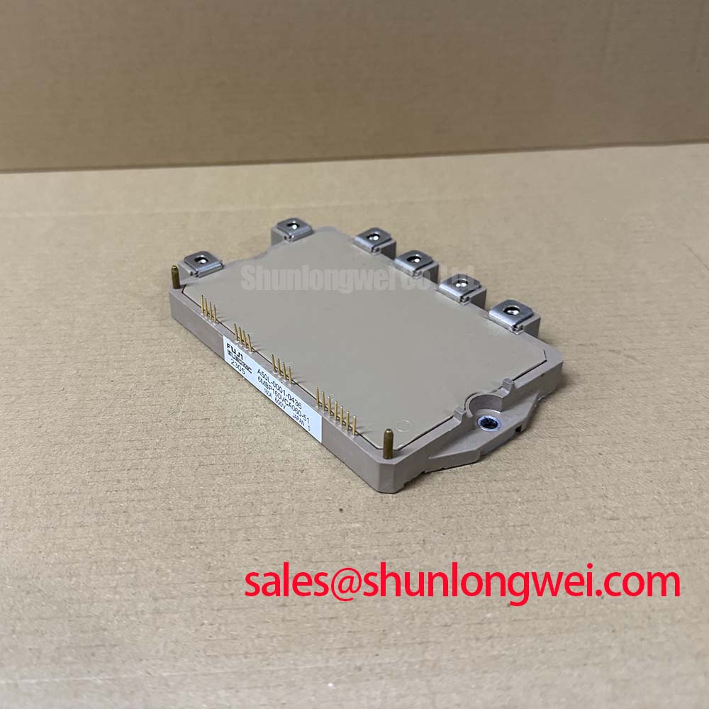
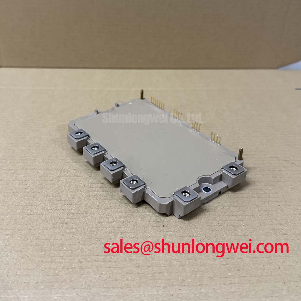
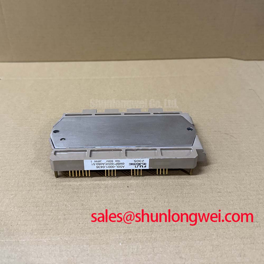
Begin service acceptance by checking the nameplate against the required electrical boundary, inspecting the power terminals and baseplate for handling damage, and confirming that the replacement unit is completely isolated before any resistance or continuity measurement. The Fuji Electric 6MBP160VCA060-51 is an intelligent power module for industrial inverter and power-conversion equipment, with an official 600 V collector-emitter voltage rating and 160 A DC collector current rating.
| Parameter | Official Specification |
|---|---|
| Manufacturer | Fuji Electric |
| Product category | IPM Module |
| Collector-emitter voltage, VCES | 600 V |
| Collector current, DC, IC | 160 A |
| Collector-emitter saturation voltage, typical, VCE(sat) | 2.2 V |
| Maximum junction temperature, Tj max | 150 °C |
| Isolation voltage, VISO | 2500 V AC for 1 minute |
| Integrated protections | Short circuit, over-current, under-voltage, and over-temperature |
These ratings and typical values are subject to the conditions specified in the applicable Fuji Electric documentation. The listed protection functions support fault supervision inside the power-conversion assembly, but they do not remove the need for system-level current limiting, suitable gate-drive sequencing, DC-link discharge control, and verified protective coordination. The official electrical data should be checked against the original inverter service documentation before installation.
When this IPM is evaluated for a commercial string inverter or micro-grid energy-storage converter, thermal work should start with the actual switching profile rather than the nominal current label. The 160 A DC collector-current rating and the typical 2.2 V VCE(sat) value describe important device characteristics, while the resulting heat in service depends on conduction duration, switching frequency, load current, modulation method, ambient temperature, cooling airflow, and the thermal path from the mounting surface to the heatsink.
Design Consideration: inspect the heatsink fins, fan path, duct seals, and air inlet for dust accumulation before attributing a high-temperature trip to the semiconductor. Thermal resistance at the interface can also change as thermal compound dries, migrates, or becomes unevenly compressed. During preventive maintenance, compare the temperature rise at comparable load points and record whether the increase occurs during conduction, switching, or both. A changing temperature pattern is more useful than a single surface-temperature reading.
For pulsed overloads, the junction does not respond instantaneously to every current variation. The transient thermal response follows the package, baseplate, interface material, heatsink, and enclosure as a series of thermal time constants. Engineers should therefore evaluate the complete overload waveform and use the manufacturer’s applicable transient thermal data when available. A multi-stage RC thermal model can help estimate junction response, but the result remains an engineering calculation that requires correlation with measured case temperature and the actual duty cycle.
For battery charge and discharge systems, bidirectional DC-DC operation can produce repeated thermal swings even when average power appears acceptable. The maintenance team should trend case temperature, heatsink temperature, fan status, and fault history over representative charge and discharge cycles. If the thermal trend changes after a service interval, inspect the cooling path and interface condition before changing switching parameters. Fuji Electric’s Power Semiconductors Portal provides the appropriate manufacturer context for reviewing power semiconductor documentation.
6MBP160VCA060-51 Operational Boundaries: Evaluating Four-Quadrant Power Flow Topologies for Grid Limits
Four-quadrant power flow requires the inverter and its control system to manage positive and negative power transfer between the DC battery rack and the AC-side network. In a micro-grid storage installation, the module may experience transitions between charging, discharging, regeneration, and standby states. These transitions should be assessed with the actual DC-link voltage, current command, modulation sequence, and protection timing used by the system.
Engineering Recommendation: minimize the commutation loop area and keep the high-current path compact and symmetrical so that stray inductance does not create excessive turn-off voltage overshoot. The critical quantity is not a universal layout number; it is the measured voltage peak at the module terminals under the fastest intended current transition. Verify the peak against the 600 V VCES boundary and the system’s required operating margin during switching tests.
A laminated busbar arrangement may reduce loop inductance, but the final result depends on conductor spacing, overlap, current sharing, terminal geometry, and the position of the DC-link capacitors. Film capacitors used for high-frequency commutation should be placed according to the switching current path, not simply near the converter cabinet entry. Snubber selection and placement are system decisions that require oscilloscope measurements at the module terminals. Do not infer safe transient behavior from DC-link voltage alone.
Phase-controlled rectifier stages connected to the DC link can introduce low-frequency ripple and higher harmonic currents when the conduction angle changes. The rectifier control strategy, line impedance, filter design, and grid-code requirements determine the appropriate mitigation. When the converter includes a bidirectional DC-DC stage, coordinate its current loop with the inverter modulation so that rapid battery current commands do not create avoidable cyclic thermal stress.
For topology review and service comparison, engineers can consult Resonant Topologies in Home Appliances as a reference for examining switching paths and commutation behavior. The article is not a substitute for the original circuit schematic or the Fuji Electric application data relevant to this device.
Where a different current class or circuit arrangement is being assessed, the 6MBI100L-060 may be reviewed as a separate product record. Compatibility must be established from voltage, current, protection, mechanical, terminal, and control requirements rather than from package appearance alone.
Preventing Spurious Faults: Baseplate Convexity Compensation and Screw Guidelines for 6MBP160VCA060-51
Before mounting, clean the heatsink surface and inspect it for burrs, embedded debris, corrosion, or local deformation. The baseplate and heatsink must make consistent contact across the intended mounting area. A thin and even thermal interface layer is generally preferred as a Design Consideration, but the material type, application method, surface finish, and permissible thickness should follow the module documentation and the selected thermal interface supplier’s instructions.
Baseplate flatness and local convexity can influence interface pressure. Excessive pressure at one region may leave another region poorly coupled, while an uneven heatsink can introduce mechanical stress into the package. Use the specified mounting locations and tighten the screws in the recommended sequence, bringing the module down progressively rather than fully tightening one corner first. The actual torque value must come from the applicable Fuji Electric mechanical instructions or approved assembly procedure.
⚠️ Maintenance Note: isolate and discharge the converter before disconnecting cables, then check the heatsink airflow and interface condition whenever contact temperature rises abnormally during a comparable load test.
Terminal inspection should include signs of discoloration, loosened hardware, cracked insulators, and conductor movement. A loose power connection can create localized heating and electrical noise, but the observed symptom should be verified through thermal imaging, torque verification under the approved procedure, and comparison with a known-good phase. Avoid treating one hot terminal as proof of a failed module without checking current balance and the upstream busbar connection.
During replacement, confirm the original gate-control connector arrangement, auxiliary supply requirements, fault feedback logic, and mechanical clearances. The integrated short-circuit, over-current, under-voltage, and over-temperature protections should be incorporated into the system fault response, not bypassed during commissioning. Any temporary test configuration should include controlled DC-link charging and a safe method for observing fault output behavior.
Field Diagnostics & Commissioning: Common-Mode Transient Immunity in Harsh 6MBP160VCA060-51 Topologies
Commissioning should begin with power removed and the control wiring documented. Confirm connector orientation, insulation condition, gate-drive supply sequencing, and fault feedback continuity before applying the DC link. The official isolation specification is 2500 V AC for 1 minute; this is a product rating and should not be presented as an automatic certification of the complete inverter insulation system.
Common-mode disturbances can arise from rapid switching-node movement, cable capacitance, enclosure bonding, probe placement, and unequal return paths. If an unexpected protection event occurs, compare the gate command, auxiliary supply, fault signal, and switching-node waveform at the same time. An oscilloscope with suitable isolation and bandwidth should be used according to the laboratory safety procedure. A fault may involve control timing, grounding, parasitic coupling, insufficient decoupling, or an actual power-stage problem, so the signal path should be checked before replacing the module.
Design Consideration: keep gate-drive and power-current return paths controlled, separate sensitive fault-feedback wiring from high dv/dt conductors where practical, and verify the shield and cabinet bonding strategy against the complete converter layout. Do not assign a specific common-mode transient immunity value to this product unless it is stated in the applicable manufacturer documentation. The system engineer must validate the assembled inverter under the intended switching conditions, temperature range, and fault sequence.
For a suspected protection event, record DC-link voltage, phase current, gate command status, fault output timing, heatsink temperature, and the operating direction of power flow. Check whether the event repeats at a defined transition or only under a particular cable configuration. The integrated protection functions can stop a damaging event, but the protective threshold, response timing, and reset behavior should be verified from the relevant control documentation before commissioning is signed off.
Use the Fuji Electric Europe semiconductor resource alongside the original equipment documentation when confirming application information. Compatibility with commercial string inverters and micro-grid energy-storage equipment remains dependent on the complete electrical, mechanical, thermal, insulation, and control design.