

Content last revised on September 23, 2026
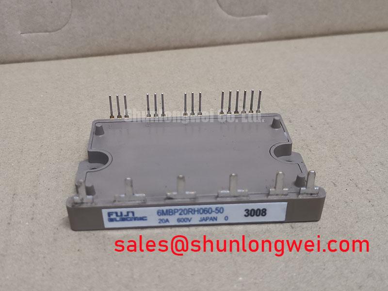
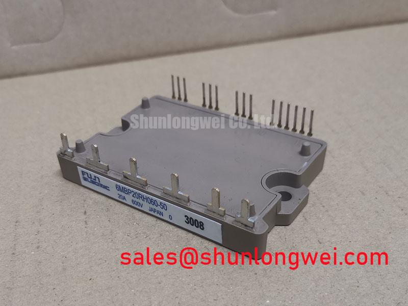
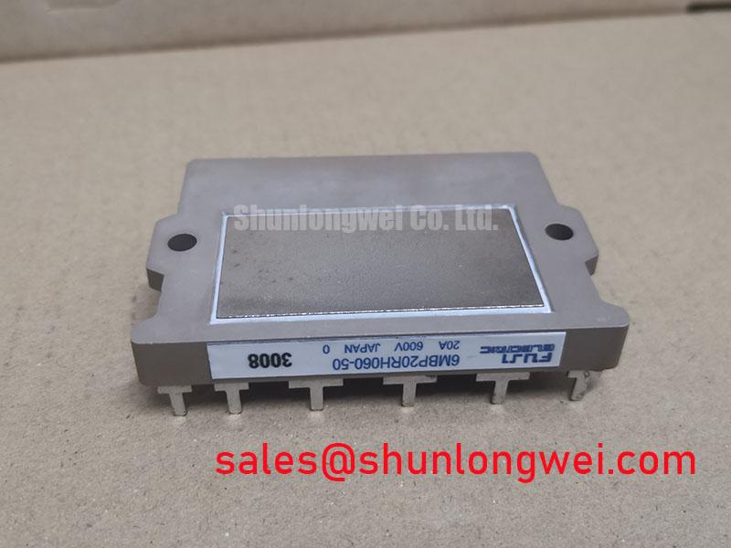
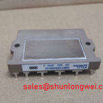
6MBP20RH060-50 Fuji Electric 600V 20A IPM Module
Begin incoming inspection by confirming the Fuji Electric marking, checking the module body for visible damage, and comparing the nameplate rating with the equipment service record. The 6MBP20RH060-50 is identified here as a 600.0 V, 20.0 A Fuji Electric IPM Module in a module package, based on the supplied product data. Before connecting a replacement to a precision stepper or BLDC servo actuator, isolate the DC bus, discharge stored energy according to the machine service procedure, and document the original terminal wiring.
A cold-state inspection should include a controlled diode-mode check between the relevant power terminals, using the known-good module or the manufacturer’s terminal diagram as the comparison reference. A multimeter reading is useful for identifying an open or unexpectedly low-impedance path, but it is not a substitute for a full semiconductor test. Gate control terminals should not be driven during a resistance or diode check, and the system integrator should verify the exact terminal assignment from the original Fuji Electric documentation before applying any auxiliary supply.
| Parameter | Supplied official product data | Engineering use |
|---|---|---|
| Manufacturer | Fuji Electric | Confirm the replacement matches the installed control platform |
| Model | 6MBP20RH060-50 | Use the complete ordering designation in procurement records |
| Rated voltage | 600.0 V | Compare with the measured DC-link and switching transient environment |
| Rated current | 20.0 A | Evaluate current, overload, switching, and thermal conditions together |
| Package | Module | Verify mechanical footprint, terminal arrangement, and heatsink interface |
Fuji Electric’s power semiconductor and IPM module information should be consulted for application documentation that is not included in the supplied product data. This product page does not assign a guaranteed switching frequency, thermal resistance, isolation rating, protection threshold, or allowable overload profile to the individual model without a supporting datasheet.
6MBP20RH060-50 Thermal-Electrical Optimization: Optimizing Gate Drive Loop Geometry for Practical Tuning
For a precision stepper or BLDC servo actuator, begin layout review at the gate-drive connector and trace the complete control-return path to the module. The gate signal loop should be compact, direct, and physically separated from the high-current commutation path. This is a Design Consideration, not a model-specific guaranteed layout requirement. The purpose is to reduce unwanted coupling that can appear as false gate movement, ringing, or inconsistent turn-off behavior during oscilloscope testing.
Where the module provides separate control and power return connections, keep the auxiliary emitter or control return routed independently from the main emitter current path until the intended reference point. Sharing a long high-current copper section can introduce emitter mutual coupling. During commissioning, compare the gate-to-emitter waveform at the module terminals rather than at the controller board. A waveform that looks clean at the driver but becomes distorted at the module may indicate excessive loop inductance, common impedance, probe placement error, or a grounding problem.
Clearance should be evaluated around the complete switching node, including copper edges, fast terminal transitions, mounting hardware, and nearby sensor wiring. The required creepage and clearance values depend on the working voltage, pollution environment, insulation system, and applicable equipment standard; they should be calculated by the system designer rather than assumed from the module name alone. Keep current-sense and encoder wiring away from the commutation loop, then validate position feedback stability while the actuator is accelerating and decelerating.
Thermal optimization also begins with the mechanical interface. The mounting surface should be clean and flat, and any thermal interface material should be applied consistently according to the material supplier’s process instructions. The module’s actual case temperature, heatsink temperature, ambient condition, switching pattern, and airflow all affect junction-temperature estimation. A transient thermal impedance curve, if supplied in the applicable Fuji Electric datasheet, should be used for pulse-load analysis; it should not be replaced by a generic value from another module family.
Benchtop Waveform Tuning: Mitigating Stress via Turn-Off di/dt-Induced Vpeak Clamping on 6MBP20RH060-50
During a bench test, place the high-voltage differential probe close to the module power terminals and observe the DC-link voltage during turn-off, regeneration, and abrupt actuator deceleration. The practical relationship is that the switching overshoot rises with stray inductance and the rate of current change; engineers may express this behavior as the DC-link voltage plus an inductive term associated with stray inductance and current slew rate. This is an Engineering Calculation used to interpret a waveform, not an additional official rating for the 6MBP20RH060-50.
Busbar geometry should minimize the area of the commutation loop. A laminated or closely coupled arrangement may be evaluated where suitable, while the final structure must be checked for insulation, mechanical strength, creepage, and service access. Snubber selection should be based on measured ringing frequency, energy, capacitor pulse capability, resistor loss, and the actual switching waveform. Do not transfer a capacitor value from a different voltage or module family without testing its effect on overshoot and turn-on loss.
When modules are used in a parallel power stage, symmetrical copper paths and similar thermal conditions are important Design Considerations. Static current distribution can be influenced by the positive temperature coefficient commonly associated with the on-state voltage of many IGBT structures, but dynamic sharing also depends on gate-loop impedance, driver timing, stray inductance, and device tolerances. The designer should verify each branch with current probes and thermal measurements rather than inferring equal sharing from identical schematic symbols.
For a replacement evaluation, record the cold-state diode readings, gate-to-emitter resistance observations, terminal-to-case insulation test conditions, and first powered waveform. The insulation test voltage and duration must come from the equipment safety procedure and the applicable module documentation. A result that differs from the original unit may indicate a wiring, probe, or surrounding circuit issue, so compare the complete signal path before assigning a failure mechanism.
💡 Bench Tip: Use ESD controls, keep the module fully isolated from the control board during cold checks, and compare every reading with a documented known-good reference before energizing the DC link.
For a field repair involving a compatible power-stage position, engineers may also review the neutral product information for 7MBR20UF060; electrical, mechanical, thermal, and control compatibility must be confirmed independently before any substitution decision.
6MBP20RH060-50 Thermal-Electrical Optimization: Cosmic Ray Robustness and Voltage Derating Practical Tuning
High-altitude operation and elevated-energy particle exposure belong to the system reliability assessment, not to an assumed feature claim for this module. A 600.0 V rating identifies the supplied voltage class, but it does not establish a universal operating voltage for every DC-link condition, altitude, switching profile, or cooling arrangement. No FIT rate, Single Event Burnout probability, altitude derating curve, or service-life figure is assigned here because those values require an authoritative device or reliability source.
For equipment installed above typical industrial elevations, the engineering review should identify the actual DC-link voltage distribution, repetitive transient amplitude, enclosure altitude, cooling performance, and fault-clearing response. The design team can then compare measured peak voltage and steady-state operating voltage with the manufacturer’s supported limits and any applicable reliability guidance. The review should distinguish between cosmic-ray or neutron-related risk, ordinary electrical overstress, inadequate isolation, and thermal overstress; field symptoms alone cannot reliably separate these mechanisms.
Use a controlled high-voltage test procedure with appropriate probes and barriers. Capture switching peaks at the cold and thermally stabilized conditions, then repeat during regenerative events. If the measured margin is uncertain, reduce test stress only through an approved system procedure and investigate the source of the transient. The Wide Bandgap Revolution reference provides broader context for power semiconductor switching and reliability discussions, but it does not replace the Fuji Electric documentation for this silicon IPM module.
Field Diagnostics and Commissioning: Regenerative DC-Bus Voltage Surge Dissipation in 6MBP20RH060-50 Topologies
In a servo actuator, deceleration can return motor energy to the DC link faster than the normal load or supply path can absorb it. Commissioning should therefore monitor the DC-link waveform during the most demanding controlled stop, direction reversal, and overhauling-load condition. The brake chopper, ballast resistor, control threshold, pulse rating, wiring inductance, and enclosure heat rejection must be evaluated as one system. The 6MBP20RH060-50 product data supplied here confirms the module voltage and current ratings, but it does not specify an internal braking resistor, braking energy capacity, or a complete regenerative control strategy.
Resistor selection should begin with measured regenerated energy and pulse duration rather than a nominal motor power value. The peak resistor power, repetitive duty, thermal accumulation, and fault state should be checked against the resistor manufacturer’s data. A resistor that survives one deceleration may still exceed its repetitive thermal capability during frequent indexing. The braking IGBT or chopper stage should be assessed for its voltage stress, current pulse, switching loss, gate-drive behavior, and protection coordination.
Keep the regenerative current loop short and separated from encoder, resolver, and communication wiring. Verify the braking command with an oscilloscope and confirm that the DC link remains within the complete drive system’s approved operating boundary. If the bus rises unexpectedly, inspect the voltage sensor scaling, braking command timing, resistor connections, contactor state, and mechanical load profile before concluding that the IPM is defective.
For the upstream rectifier or complementary power-stage context, engineers can review 6MBI15L-060 as a separate module reference. It should not be treated as an automatic companion or replacement for the 6MBP20RH060-50. Procurement and maintenance records should retain the full model designation, measured installation conditions, and the approved equipment drawing for any future service intervention.