


Content last revised on March 25, 2026
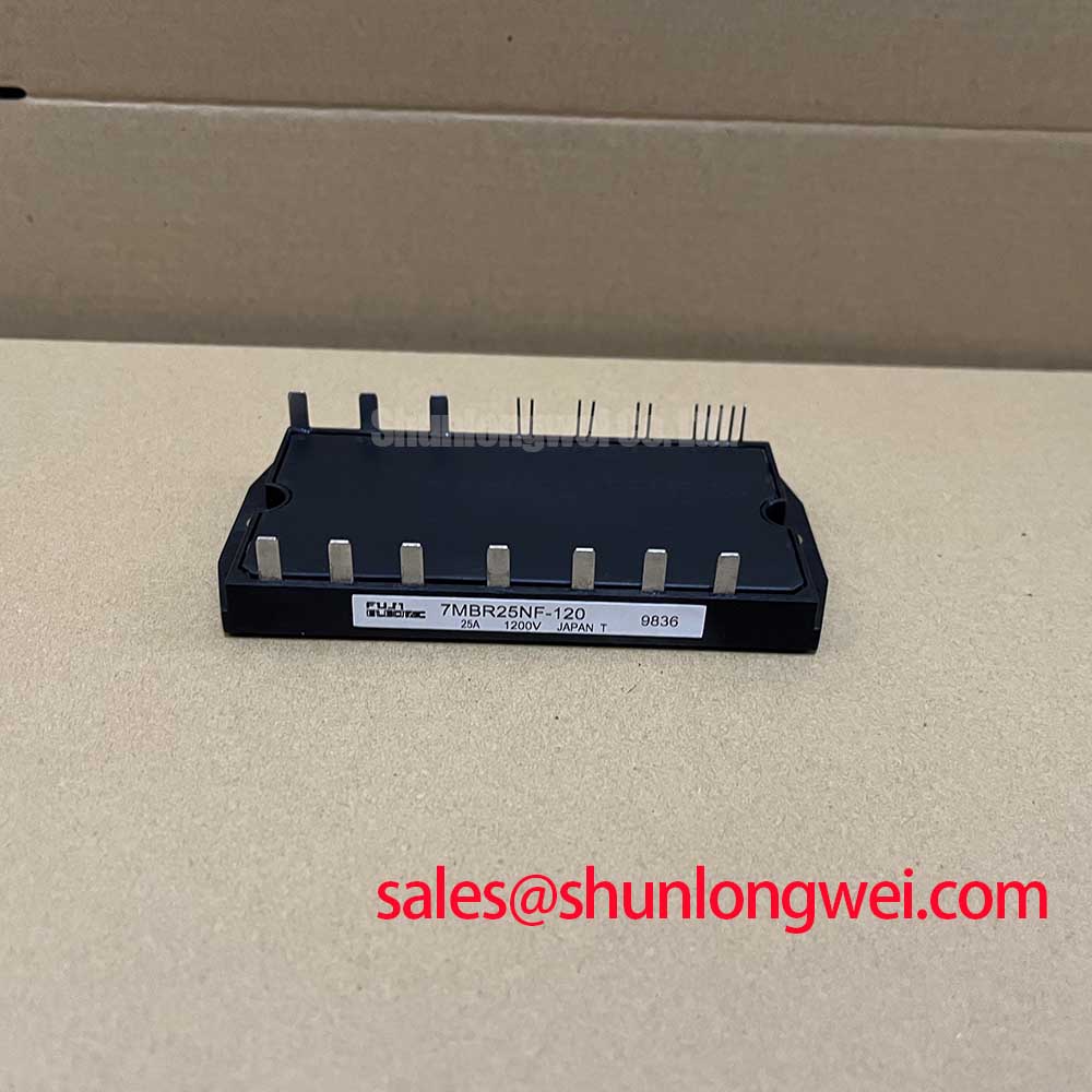
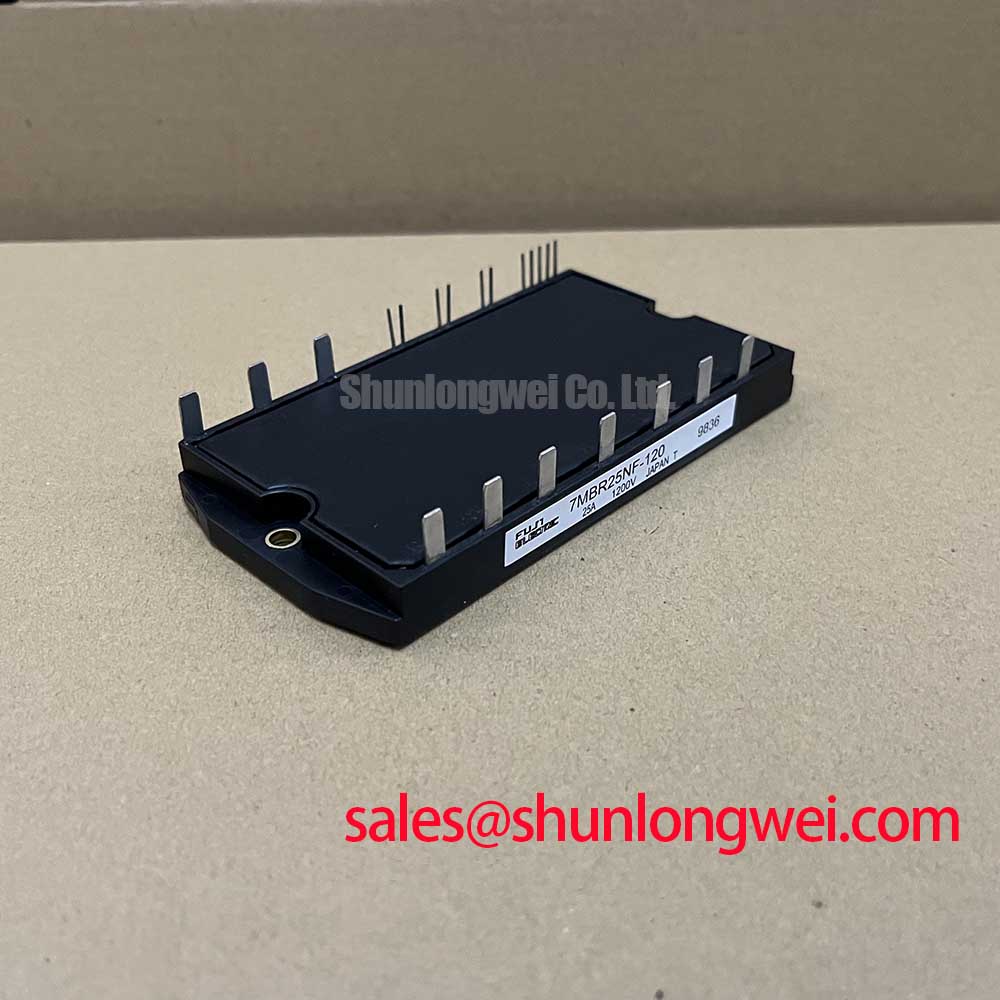
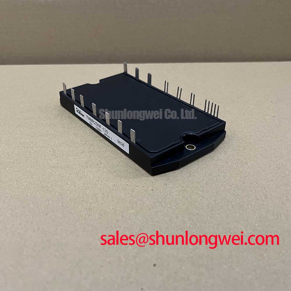
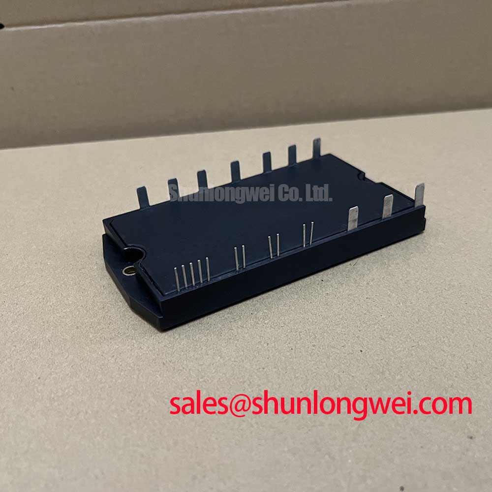
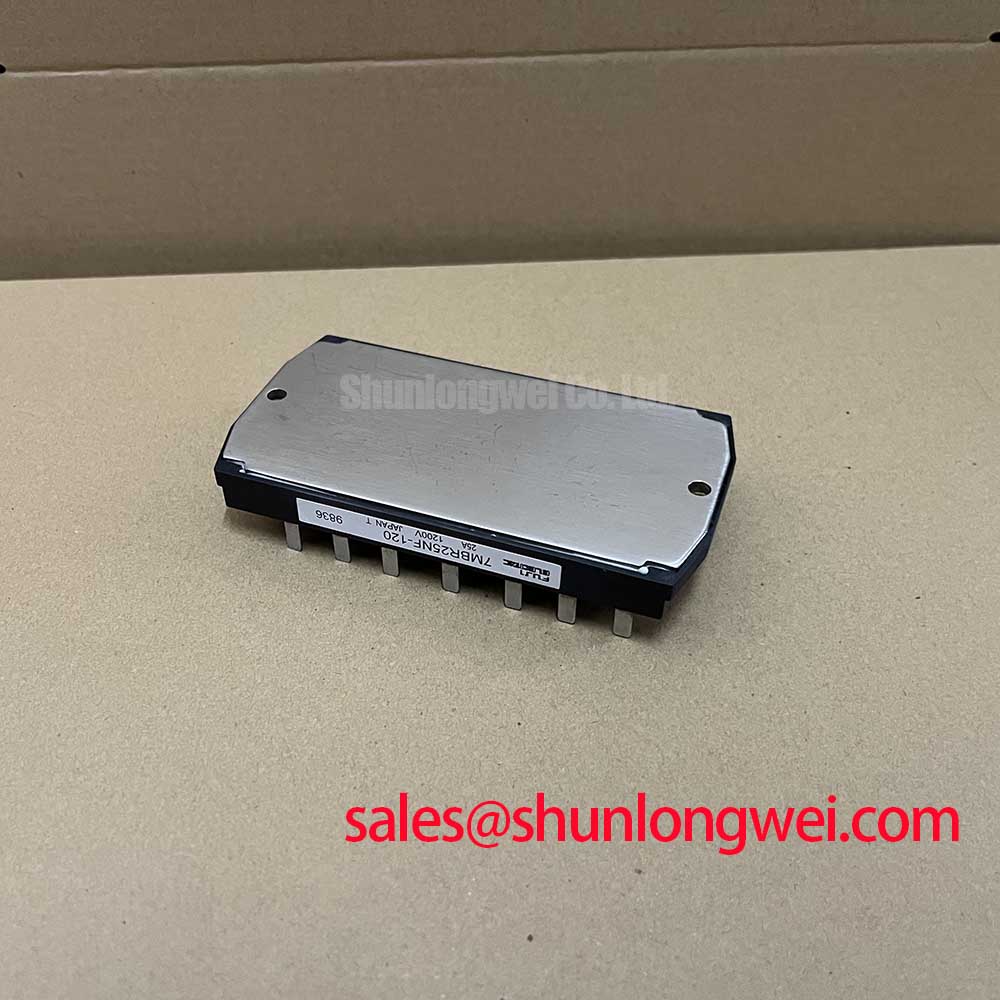
Fuji Electric 7MBR25NF-120 | Compact 1200V/25A PIM for Integrated Motor Drives
The Fuji Electric 7MBR25NF-120 is an intelligently designed Power Integrated Module (PIM) that provides a comprehensive power stage solution for low-power motor control and power conversion applications. By integrating a three-phase converter, a brake chopper, and a three-phase inverter into a single, compact package, this IGBT module dramatically simplifies system design, reduces assembly costs, and enhances overall reliability. It is engineered for designers seeking to optimize footprint and accelerate time-to-market without compromising on thermal performance or electrical robustness.
- High-Integration Design: Features a full 7-in-1 configuration (three-phase rectifier + brake IGBT/FWD + three-phase inverter) to minimize external component count and PCB complexity.
- Optimized for Low-Power Drives: With a 1200V blocking voltage and 25A nominal current rating, it is perfectly suited for AC drives, servo amplifiers, and UPS systems in the 2.2kW to 4kW range.
- Enhanced Thermal Management: Incorporates an NTC thermistor for precise, real-time temperature monitoring, enabling robust over-temperature protection.
- Proven Reliability: Built with Fuji Electric's established N-channel IGBT technology, ensuring a balanced performance between conduction and switching losses for high-efficiency operation.
Engineering Advantage: The 7-in-1 PIM Architecture
The core value of the Fuji Electric 7MBR25NF-120 lies in its sophisticated level of integration. A conventional discrete design for a motor drive requires sourcing and assembling over a dozen individual power components: six rectifier diodes, a brake IGBT and its associated freewheeling diode (FWD), and six inverter IGBTs with their FWDs. This PIM consolidates all these functions into one thermally and electrically optimized component. This architectural choice delivers tangible engineering benefits, including a significant reduction in stray inductance compared to PCB-trace-based layouts. Lower inductance minimizes voltage overshoots during switching transients, which helps to improve EMI performance and reduce the need for extensive snubber circuits. For a deeper understanding of how component integration impacts system reliability, explore our guide to IGBT failure analysis.
Optimized for Demanding, Space-Constrained Applications
The 7MBR25NF-120 is not a general-purpose component; it is purpose-built to solve specific challenges in compact power systems. Its performance characteristics make it an exceptional choice in several key areas:
- Compact Variable Frequency Drives (VFDs): In applications like conveyor belts, pumps, and fans, VFDs are often housed in tightly packed enclosures. The all-in-one nature of this module allows for the design of smaller, more power-dense, and cost-effective inverter systems.
- Robotic Servo Amplifiers: Precision and rapid response are critical in robotics. The integrated brake chopper is essential for managing the regenerative energy created during quick deceleration of servo motors, ensuring positional accuracy and protecting the DC bus from overvoltage conditions.
- Uninterruptible Power Supplies (UPS): In smaller UPS units, reliability and a simplified bill of materials (BOM) are paramount. The 7MBR25NF-120 provides a complete, factory-validated power stage that accelerates the development cycle and increases the end product's field reliability. For applications demanding higher current handling within a similar integrated footprint, the 7MBR50SB120-50 offers a direct upgrade path.
7MBR25NF-120 Key Specifications
The following table provides a summary of the critical electrical and thermal characteristics. For complete device specifications and application notes, you can download the official datasheet.
| Parameter | Value |
|---|---|
| Collector-Emitter Voltage (V_CES) | 1200V |
| Collector Current, DC (I_C) - Inverter Part | 25A (T_C = 80°C) |
| Collector-Emitter Saturation Voltage (V_CE(sat)) | 2.8V (Typical) |
| Forward Voltage, FWD (V_F) | 2.3V (Typical) |
| Max Power Dissipation (P_C) - Inverter Part | 145W |
| Operating Junction Temperature (T_j) | -40 to +150°C |
Engineer's FAQ for the 7MBR25NF-120
What are the primary thermal management considerations for this PIM?
The single, isolated baseplate simplifies heatsink design. It is crucial to ensure a low thermal resistance path by using a high-quality thermal interface material (TIM) and applying appropriate mounting pressure. The integrated NTC thermistor should be connected to the control board's monitoring circuit to provide active thermal feedback, allowing for graceful power reduction or shutdown during overload conditions, thus preventing catastrophic failure.
What type of gate drive circuit is recommended for this module?
A robust gate driver is essential for reliable operation. We recommend using a driver IC that provides galvanic isolation for the six inverter channels. For optimal performance, a gate voltage of +15V for turn-on is standard. A negative turn-off voltage (e.g., -5V to -9V) is highly advised to provide strong immunity against dV/dt induced turn-on, especially in noisy motor drive environments. For more detailed guidance, see our article on practical tips for robust IGBT gate drive design.
Is this module suitable for high-frequency switching applications?
The Fuji Electric 7MBR25NF-120 is optimized for applications in the low to moderate switching frequency range, typically from 2 kHz to 15 kHz, which is common for standard motor control. While it can operate at higher frequencies, the switching losses will increase, requiring more aggressive thermal management. Its design prioritizes a low V_CE(sat) to minimize conduction losses, making it highly efficient in its target application space. For higher frequency needs or further technical consultation, please contact our technical team to discuss alternative IGBT modules.