

Content last revised on September 19, 2026
Preventing Spurious Faults: Optimizing Heatsink Contact Pressure and Mounting Screw Guidelines for 6MBP100KC060
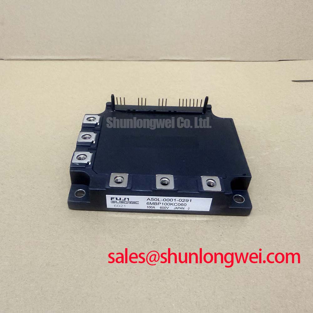
With the drive isolated and discharged, first inspect the 6MBP100KC060 baseplate, heatsink face, power terminals, and gate connections for contamination, uneven contact marks, loose hardware, or moisture residue before energizing the inverter. This Fuji Electric IPM module is officially rated at 600 V VCES, with inverter current rated at 100 A at TC = 80°C and brake current rated at 50 A.
The inverter section has an official maximum power dissipation of 390 W at TC = 25°C, while the brake section is rated at 208 W. These ratings make the thermal path from module baseplate to heatsink a practical maintenance priority. As a Design Consideration, apply thermal interface material as a continuous, controlled layer rather than relying on a thick deposit to compensate for a damaged heatsink surface. A commonly used service target is a thin layer in the 50 to 100 μm range, subject to the thermal material supplier’s instructions and the actual flatness of the mating surfaces.
Mounting screws should be tightened in a progressive diagonal sequence so that contact pressure develops evenly across the module. Check that no cable lug, busbar edge, or harness clamp transfers mechanical force into the module terminals after final assembly. Baseplate curvature, hardened thermal compound, and blocked fan paths can all contribute to elevated case temperature or intermittent protection events, but each condition should be verified by inspection and temperature measurement rather than assumed from a single fault code.
⚠️ Maintenance Note: Monitor terminal and heatsink contact temperature during normal loaded operation, then clean the cooling path and recheck fastener tightness during scheduled preventive maintenance.
For a heavy duty variable frequency AC motor drive repair, technicians can compare terminal arrangement, mechanical fit, control interface requirements, and complete electrical ratings against the original design documentation. The related 6MBI100L-060 can be assessed as a separate Fuji Electric module option, but it requires a full circuit, package, and protection compatibility review rather than an assumed direct replacement.
6MBP100KC060 Circuit Protection & Reliability: Calibrating Derating Guidelines and Mismatched Parameters
The 7 in 1 configuration combines a three phase inverter and brake function, allowing the drive designer to implement regenerative energy handling without adding a separate brake chopper transistor. Its specified inverter VCE(sat) maximum is 2.7 V under the datasheet test conditions at 100 A. This value is an official conduction characteristic, not a prediction of total inverter loss, because switching conditions, modulation, heatsink performance, and load profile remain system dependent.
As a Design Consideration, the positive temperature tendency of IGBT conduction voltage can support static current sharing in parallel arrangements after thermal equilibrium is reached. It does not eliminate the need for matched gate loop paths, symmetric busbar geometry, comparable gate driver propagation delay, and equivalent current sensing conditions. Dynamic imbalance can still occur during switching when one path has different parasitic inductance or gate damping.
Bootstrap supply integrity also deserves examination where the drive topology uses high side bootstrap circuits. An Engineering Recommendation is to size the capacitor from the measured or documented gate charge, driver quiescent current, expected switching interval, leakage contributions, and acceptable gate supply droop. The system engineer should validate that result at the actual duty cycle and minimum operating conditions. Do not infer gate charge or a fixed capacitor value for this module without the applicable driver and module documentation.
Inspect the DC link and input power stage as a connected system. In some drive architectures, a device such as the 6MBI100S-140 may be evaluated for a complementary power stage role, subject to its own voltage class, topology, thermal design, and control requirements. Fuji Electric’s power semiconductor information provides useful manufacturer context for reviewing switching device families, while the final protection settings remain determined by the complete drive.
6MBP100KC060 Thermal Electrical Optimization: Fault Clearing Dynamics and Desaturation Practical Tuning
The official short circuit withstand capability is at least 10 μs under the stated conditions of VCC = 400 V and VGE = 15 V. This is a bounded datasheet specification, not a universal system protection delay allowance. Protection sensing, signal propagation, blanking, gate discharge behavior, DC bus condition, and temperature must all be tested in the finished inverter.
A desaturation scheme can be used to identify an abnormal collector emitter voltage while a commanded switch is on. Type I and Type II fault categories should be defined by the equipment protection architecture rather than by a generic threshold. When a fault is detected, a controlled two stage soft turn off sequence may reduce inductive overshoot compared with an uncontrolled interruption. The practical objective is to limit switching stress while still removing fault current within the module’s applicable safe operating boundary.
Keep gate drive conductors separated from high current power paths where the enclosure and layout permit. Minimize the commutation loop inductance to suppress turn off overshoot, then verify peak voltage margins against the DC link voltage with suitable switching measurements. If protection trips occur only under acceleration, deceleration, or rapid load change, compare gate waveforms, DC link ripple, brake operation, cooling condition, and motor cable behavior against a known healthy drive where available.
6MBP100KC060 Thermal Electrical Optimization: Cosmic Ray Robustness and Voltage Derating Practical Tuning
No official field failure rate, terrestrial neutron susceptibility value, altitude derating curve, or single event burnout FIT figure is provided here for the 6MBP100KC060. It would therefore be inappropriate to state a quantified cosmic ray reliability level or an operating life expectation for this module.
As a Design Consideration, installations at elevated locations can warrant a system level review of insulation coordination, enclosure contamination control, cooling effectiveness, DC bus transient behavior, and the voltage stress seen by the 600 V module. The responsible system engineer should confirm applicable site requirements and validate voltage transients during the intended operating modes. This review is particularly relevant when a motor drive has long output cables, regenerative loads, or uncertain supply quality.
For long term maintenance planning, inspect for condensation traces after cold starts, confirm airflow through the heatsink channels, and replace deteriorated thermal interface material according to the equipment maintenance program. For broader context on thermal paths used in power electronics, see The Advanced Thermal Management Revolution. Fuji Electric’s global power semiconductor technologies resource can also support manufacturer level technology research when reviewing a drive refurbishment or redesign.