

Content last revised on September 21, 2026
Benchtop Waveform Tuning: Mitigating Stress via Dynamic Gate Impedance Control for Robust Operation of 6MBP200VDA060-52
With the DC link discharged and the gate-driver connectors isolated, first verify the cold-state resistance paths at the power terminals against the removed unit and inspect the module base, terminal hardware, and enclosure for cracking, corrosion, or heat-discoloration before fitting 6MBP200VDA060-52.
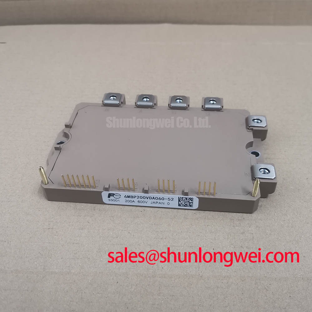
This Fuji Electric IPM module has a specified 600V voltage rating and a 200A rated current under the specified conditions in a Module package. These are Official Datasheet Specifications and define the electrical identity that must be matched when evaluating a repair replacement in industrial power equipment. The original inverter circuit, gate-drive board, heatsink condition, DC-link arrangement, protection logic, and control firmware remain system-determined factors that require verification before energisation.
| Product identification | 6MBP200VDA060-52 |
|---|---|
| Manufacturer | Fuji Electric |
| Product category | IPM Module |
| Voltage rating | 600V Official Datasheet Specification |
| Current rating | 200A Official Datasheet Specification under specified conditions |
| Package | Module Official Datasheet Specification |
For repair work involving commercial string inverters or micro-grid energy-storage converters, matching the voltage and current ratings alone does not establish drop-in compatibility. Engineers should compare the original circuit documentation, mechanical mounting arrangement, terminal positions, control connections, protection interfaces, and gate-driver behavior before selecting a replacement module. Fuji Electric’s power semiconductor and IPM module information provides useful manufacturer-level context for the product family.
Before returning a repaired power stage to service, examine gate command waveforms with the module installed in the intended driver environment. A gate signal that appears clean at the driver output can behave differently at the module connection because conductor routing, return paths, common-mode activity, and nearby power loops influence the actual switching event. This matters when a phase leg is exposed to rapid voltage movement, where unintended gate disturbance can contribute to cross-conduction or abnormal switching stress.
Design Consideration: gate-drive impedance should be treated as part of the complete switching loop rather than as an isolated resistor value. The appropriate damping arrangement depends on the installed driver, switching frequency, DC-link condition, cable length, power-loop geometry, thermal condition, and measured collector-emitter switching behavior. Engineers should capture both normal operating waveforms and startup or fault-recovery events, then verify that gate behavior remains controlled under the actual bus voltage and load conditions.
Active Miller-clamp circuits and negative gate-bias strategies are commonly evaluated where induced gate voltage is suspected during fast switching. They are not stated here as official characteristics of 6MBP200VDA060-52; they are Engineering Recommendations for the surrounding gate-drive design. Any negative-bias value, clamp threshold, or timing relationship must be confirmed against the original driver documentation and measured safely on the completed system.
On a stopped unit, a practical first check is to inspect gate-driver connectors, local decoupling components, isolation barriers, and signal return continuity before assuming the power module is responsible for unstable waveforms. A comparison against an intact channel or known-good assembly can help identify whether the abnormal behavior follows the module position, the driver board, or the measurement setup. The Fuji Electric power modules portal is also a useful reference point when reviewing module-family documentation.
⚠️ Field Alert: Disconnect and verify discharge of the DC link before removing gate or power connections, because residual energy and incorrect reconnection can damage the module and associated driver circuitry.
Benchtop Waveform Tuning: Mitigating Stress via Turn-Off di/dt-Induced Vpeak Clamping in 6MBP200VDA060-52
Turn-off overshoot should be investigated at the power terminals with a measurement arrangement suitable for the converter’s voltage and transient environment. In engineering terms, peak voltage rises above the DC-link voltage as stray inductance interacts with the changing current. The magnitude is linked to loop inductance and turn-off current rate, so a layout change, capacitor condition, busbar joint, or gate-drive adjustment can materially alter the waveform without changing the module itself.
Design Consideration: minimise the physical area enclosed by the DC-link capacitor, module power terminals, and return path to suppress inductive overshoot during turn-off. A compact, mechanically secure bus structure and appropriately located DC-link capacitance can reduce the loop contribution, but the acceptable peak level must be validated by the system engineer against the 600V module rating, actual switching transients, protection response, and the equipment manufacturer’s operating limits.
Inspect each power-terminal interface for correct alignment, clean contact surfaces, and even clamping pressure. Loose or distorted busbars can introduce resistance, inductance, and local heating that are not apparent from a visual check alone. In vibration-prone industrial enclosures, recheck fastening after the first controlled thermal run, following the original equipment’s mechanical instructions rather than applying an assumed torque value.
Snubber capacitors and clamping networks should be assessed as system components, not generic add-ons. Their suitability depends on the measured ringing frequency, circulating energy, capacitor ripple capability, circuit placement, and thermal environment. Where oscilloscope traces show inconsistent overshoot between phases, compare the physical conductor routes, DC-link capacitor connections, probe placement, and gate timing before drawing conclusions about the module.
For a related lower-current power-module reference during a documented hardware review, engineers can examine 6MBI100L-060. It should be evaluated only against the original circuit requirements; its presence in the same voltage class does not establish direct replacement compatibility for the 200A unit.
6MBP200VDA060-52 Circuit Protection & Reliability: Assessing High-Altitude Cosmic-Ray-Induced SEB Failure
For equipment operated at elevated altitude, do not assign a cosmic-ray or single-event burnout rate to 6MBP200VDA060-52 without a relevant manufacturer specification, qualified test report, or application-specific reliability analysis. No field failure rate, lifetime figure, or altitude derating number is stated here. Such values depend on semiconductor construction, applied voltage, converter topology, thermal loading, location, operating altitude, and mission profile.
Design Consideration: evaluate the installed DC-bus operating range, transient peaks, protection thresholds, cooling condition, and fault-clearing sequence together when the equipment will be used in environments that differ materially from its original design conditions. The decision should be based on approved system documentation and verified measurements, not on an assumed universal derating rule.
A repair bench can still identify several immediate risks without making unsupported reliability claims. Confirm that the protection controller detects abnormal current conditions, verify that gate commands are removed during a fault event, and examine the DC-link capacitors, precharge path, contactors, current sensors, and control-power stability. A semiconductor fuse, where included by the equipment design, must be assessed by its published time-current and energy characteristics in relation to the complete protection scheme. Its performance cannot be inferred solely from the module’s 200A current rating.
Transient thermal behavior is also system-dependent. A short overload pulse can create a different junction response from steady current because heat moves through several thermal paths over time. Engineers should use the original equipment thermal design, measured heatsink condition, airflow verification, and approved module documentation to assess pulse capability. Do not convert a cold resistance check or a brief no-load run into a lifetime prediction.
For broader engineering context on module selection, protection coordination, switching tests, and reliability assessment, see the Power Electronics Masterclass. It is a technical reference for system evaluation rather than a substitute for the specific converter documentation.
Transient Dynamics & Electrical Design: Isolated DC-DC Power Supply Sizing for High-Reliability Operation of 6MBP200VDA060-52
When replacing an IPM module in an inverter assembly, verify the isolated gate-drive supply under normal switching, startup, shutdown, and protection operation. The drive supply must maintain the operating conditions required by the existing gate-driver circuit while keeping control-side and power-side references correctly separated. Supply capability, isolation coordination, common-mode transient behavior, and undervoltage response are properties of the complete driver implementation, not published official parameters of this module based on the available product data.
Engineering Recommendation: review the isolation barrier specification of the existing driver and DC-DC supply, then test for unintended gate pulses during representative switching transitions. A driver that loses stable bias, suffers excessive common-mode disturbance, or recovers unpredictably after a protection event can produce symptoms that resemble a module fault. Verify the control supply waveform and driver output at the module interface before replacing power hardware again.
For commercial string inverter and micro-grid energy-storage repair, assess the input rectification, DC-link, inverter bridge, current measurement, and control-power sections as connected subsystems. A complementary device such as 6MBI15L-060 may appear in associated power circuitry, but its role and suitability must be established from the actual schematic and bill of materials.
After installation, perform a controlled commissioning sequence specified by the equipment manufacturer. Check for correct mechanical seating, insulation condition, power-terminal continuity, driver connection integrity, cooling-path contact, and protection feedback before applying full operating load. This approach keeps the evaluation focused on the verified identity of 6MBP200VDA060-52 as a 600V, 200A Fuji Electric module while leaving converter-specific design limits to the responsible system engineer.